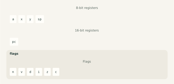
This specification is the sole processor-specific implementation source for Dromaios's
instruction-level NMOS 6502. It defines stored state, all 151 documented forms,
status views, reset, execution, external interrupt entry, and the public interface.
Its cpu fences generate production code; preceding paragraphs supply instruction
explanations. Shared TypeScript services provide recording, validation, and byte
dispatch according to these declarations.
The model records instruction-level effects in order. It does not describe cycles or dummy reads. If a memory access fails, execution stops at that access: earlier effects remain and later effects do not occur. See the public contracts below and the language guide for this prototype's syntax and boundaries.
History · Programmer's machine · State · Addressing · Arithmetic · Byte updates · Status · Stack · Control flow · Worked execution · Reset · Interrupts · API · Checks
Model boundary
Cpu6502 models the original MOS 6502 (NMOS), connected to flat
64 KiB RAM. This is not
a 65C02 or the NES's Ricoh 2A03 variant.
One step() attempts one instruction. The CPU has no example-completion
address or synthetic halted latch; the caller decides when to stop stepping.
All documented opcode forms are implemented. Records remain instruction-level:
cycle timing, dummy bus reads, electrical interrupt lines, undocumented opcodes,
devices, and browser controls are unmodeled. External entry uses the explicit
boundary offer below.
Historical background
MOS Technology introduced the 6502 in 1975 at a price of $25. Chuck Peddle led a team that included former Motorola employees; the low price made it practical to consider a processor in products with modest budgets. The Computer History Museum's 1975 timeline places the introduction in that context. The following year's KIM-1 gave engineers a small computer for experimenting with the processor, and also attracted hobbyists.
The Synertek/MOS programming manual introduces a byte accumulator, two byte index registers, and a sixteen-bit program counter. Addressing modes make those few registers useful across a full 64 KiB address space. This specification follows the original NMOS model; later CMOS instruction additions and behavior changes are not implied by the name 6502.
The programmer's machine
Addresses and data below use $ for hexadecimal. A byte holds $00–$FF;
a sixteen-bit address holds $0000–$FFFF. Assembly # marks an immediate
value: LDA #$80 loads the number $80, while LDA $80 loads the byte from
memory address $0080.
| State | Role |
|---|---|
| A | Accumulator for arithmetic, logical operations, and many transfers |
| X, Y | Index registers, also useful as counters and byte storage |
| PC | Address of the next instruction byte |
| SP | Eight-bit stack offset into page one, $0100–$01FF |
| N, Z | Sign bit and zero result from instructions that update them |
| C | Arithmetic carry; comparison and subtraction use set C for no borrow |
| V | Signed arithmetic overflow, or memory bit 6 copied by BIT |
| D | Select decimal arithmetic for ADC/SBC |
| I | Mask ordinary interrupt requests |
X and Y are separate byte indices; they do not combine into a word register.
The stack uses its own page and wraps its byte offset there. Zero page,
$0000–$00FF, has compact address operands and can also hold word pointers.
A sixteen-bit word is stored low byte first: $34 $12 denotes $1234.
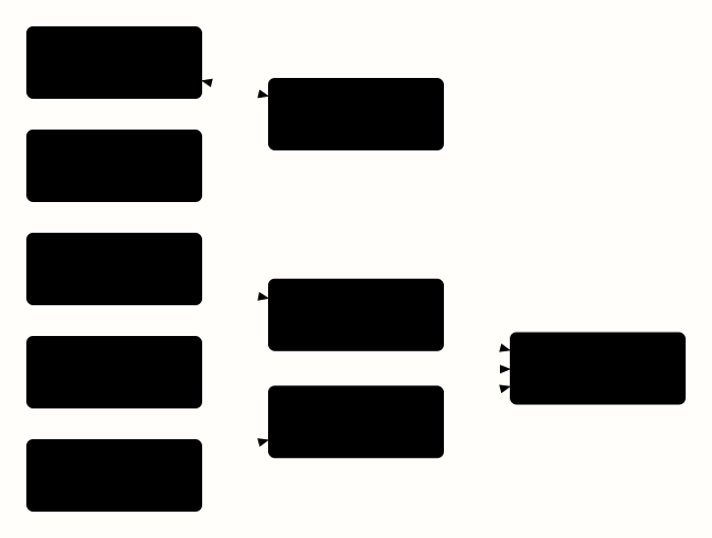
Diagram source
<diagram padding="24" theme="light" background="#fffefa">
  <graph direction="lr" gap="28" row-gap="60">
    <rect id="a" width="160" height="66">A: accumulator</rect>
    <rect id="alu" width="160" height="66">Arithmetic and logic</rect>
    <rect id="flags" width="160" height="66">N V D I Z C</rect>
    <rect id="indices" width="160" height="66">X and Y</rect>
    <rect id="addressing" width="160" height="66">Address calculation</rect>
    <rect id="memory" width="160" height="66">64 KiB memory</rect>
    <rect id="pc" width="160" height="66">PC</rect>
    <rect id="sp" width="160" height="66">SP</rect>
    <rect id="stack" width="160" height="66">Page-one stack</rect>
  </graph>
  <connect from="a" to="alu" arrow="both"/>
  <connect from="flags" to="alu" arrow="none"/>
  <connect from="indices" to="addressing"/>
  <connect from="addressing" to="memory"/>
  <connect from="pc" to="memory"/>
  <connect from="sp" to="stack"/>
  <connect from="stack" to="memory"/>
</diagram>
This is a functional map of the model. It helps distinguish an index, an address, and the byte at that address; it does not describe physical wiring or timing. Memory-mapped devices use the surrounding machine's address space; there are no separate IN/OUT instructions in the documented 6502 inventory.
Stored state
The declarations below generate the schema used by construction, snapshots, machine parsing, and every instruction definition. They retain the public lowercase fields and their declaration order. Initial values are supplied by the caller; declaring storage does not choose power-on or reset values.
Only six arithmetic/control flags are stored. The packed status byte's fixed bit 5 and stacked B marker are not extra state fields. The specification owns their packing and restoration; reset and interrupt recognition are defined in the public contract below. Changing a register does not implicitly recalculate flags: LDA sets N/Z explicitly, while TXS leaves all six flags unchanged.
cpu "6502"
state {
  register A: 8
  register X: 8
  register Y: 8
  register SP: 8
  register PC: 16
  flag N
  flag V
  flag D
  flag I
  flag Z
  flag C
}
State and initialization
The specification's stored-state declaration
generates the schema used by construction, snapshots, and machine parsing.
Cpu6502State contains a, x, y, sp, pc, and flags.
Cpu6502Flags contains booleans n, v, d, i, z, and c.
I masks explicit IRQ offers, with the opposite sense to the 8080's
interrupt-enable latch. It does not mask NMI or BRK. The six flags are stored individually; the
status stack encodes and restores them as a byte. B and the
unused status bit are not stored fields or new snapshot properties.
Memory uses the byte-connection contract, with RAM as the usual connection.
new Cpu6502(ram, initialState: Cpu6502Snapshot) requires a 64 KiB byte-memory address space
and copies only declared state fields, including flags, into CPU-owned storage.
It performs no reset, vector reads, or instruction fetches. A, X, Y, and SP
must be integers in 00–FF; PC must be an integer in 0000–FFFF. Invalid
numeric values or address-space size throw RangeError; non-boolean flags throw TypeError. Extra input
properties are ignored. Declared fields may be supplied through getters,
including inherited and non-enumerable fields; each is copied once before
validation.
Initial registers and flags are explicit caller choices, not power-on or reset
defaults. SP is an 8-bit offset within page 01. Flags are stored state:
supplying A = 00 does not implicitly set Z.
Values exposed in records are numbers; hexadecimal formatting belongs to presentation. PC and operand fetching wrap at 16 bits. RAM's host API validates addresses and values instead of wrapping them.
Snapshots and ownership
snapshot() returns a detached Cpu6502Snapshot with recursively readonly
TypeScript fields. Records have the same ownership guarantees: later CPU or
RAM changes cannot alter them, and edits made by JavaScript to returned values
cannot change live state. Readonly typing does not require runtime freezing.
Snapshots copy CPU state, not RAM, and inspection performs no RAM accesses.
Step records
The CPU-specific Cpu6502StepRecord has these fields:
| Field | Meaning |
|---|---|
instruction |
Non-null { address, bytes } from the attempted instruction |
before, after |
Complete detached CPU snapshots |
accesses |
Ordered { kind, address, value } entries, with kind read or write |
outcome |
executed or unsupported |
reason |
Present only with unsupported: opcode |
The outcome/reason relationship is a discriminated union. All public record
fields, nested snapshots, byte arrays, and access entries are readonly. There
is no halted or complete CPU outcome in this model, and no null instruction. External interrupt records are a separate type.
Instruction bytes come from the actual opcode and operand reads. Data reads
and writes appear only in accesses. Record the actual accesses during execution,
without rereading an instruction or the old contents of a write destination.
These records omit dummy reads and carry no cycle-count claim. BRK consumes
and records its following padding byte, so its instruction bytes contain two
bytes even though the documented opcode length is one.
Unsupported instructions
Opcodes outside the coverage inventory return
unsupported with reason opcode, read only the opcode, and leave CPU state
and RAM unchanged. Repeating the call repeats that read; it does not advance
past the limitation. The caller must stop on unsupported results and use a
bounded instruction budget when running programs.
Addressing a byte
An address source returns a sixteen-bit address without reading the final data
byte. This distinction lets LDA read that byte and STA write it. Each source has
its own capture scope. fetch consumes the next instruction byte; register
reads live state at that point. An expression uses already captured values.
Zero-page addressing extends an eight-bit offset to sixteen bits. For indexed
zero-page addressing, addition happens before extension: $FF + $01 wraps
to $00. The Y variant serves LDX/STX; LDA and STA use the X variant.
source zeroPage "zero page": 16 {
  offset = fetch
  return extend(offset, 16)
}
source zeroPageX "zero page indexed by X": 16 {
  offset = fetch
  index = register X
  return extend(add(offset, index), 16)
}
source zeroPageY "zero page indexed by Y": 16 {
  offset = fetch
  index = register Y
  return extend(add(offset, index), 16)
}
Absolute addresses arrive low byte first. concat(high, low) joins the two
bytes into a word. For indexed absolute addressing, the index is extended before
addition, so a carry crosses a page boundary and $FFFF + $01 wraps to $0000.
source absolute "absolute address, low byte first": 16 {
  low = fetch
  high = fetch
  return concat(high, low)
}
source absoluteX "absolute indexed by X": 16 {
  low = fetch
  high = fetch
  index = register X
  return add(concat(high, low), extend(index, 16))
}
source absoluteY "absolute indexed by Y": 16 {
  low = fetch
  high = fetch
  index = register Y
  return add(concat(high, low), extend(index, 16))
}
The two indirect modes read a low-first pointer from zero page. In both modes,
the pointer's high-byte address wraps within zero page: a pointer at $FF reads
its high byte from $00, not $0100. u8($01) makes the width of that addition
explicit. Indexed indirect adds X before reading the pointer; indirect indexed
reads the complete pointer before reading Y and adding it to the address.
source indexedIndirect "indexed indirect (zero page,X)": 16 {
  offset = fetch
  index = register X
  pointer = add(offset, index)
  low = memory(extend(pointer, 16))
  high = memory(extend(add(pointer, u8($01)), 16))
  base = concat(high, low)
  return base
}
source indirectIndexed "indirect indexed (zero page),Y": 16 {
  offset = fetch
  pointer = offset
  low = memory(extend(pointer, 16))
  high = memory(extend(add(pointer, u8($01)), 16))
  base = concat(high, low)
  index = register Y
  return add(base, extend(index, 16))
}
An immediate operand is the next instruction byte itself. It has no destination address, so it is available to loads but cannot be selected by a store.
source immediateByte "immediate byte": 8 {
  byte = fetch
  return byte
}
Encoding the addressing mode
The accumulator families share aaa bbb 01. The operation bits aaa select
ORA/AND/EOR/ADC/STA/LDA/CMP/SBC in binary order. The three b
bits select the following modes in binary order. A memory entry provides
both its address and the byte read there; a
value entry provides only a value. Selecting .address therefore omits the
immediate encoding, rather than inventing an immediate STA instruction.
operands accumulator {
  000 "(zero page,X)" = memory indexedIndirect
  001 "zero page" = memory zeroPage
  010 "#byte" = value immediateByte
  011 "absolute" = memory absolute
  100 "(zero page),Y" = memory indirectIndexed
  101 "zero page,X" = memory zeroPageX
  110 "absolute,Y" = memory absoluteY
  111 "absolute,X" = memory absoluteX
}
Loading A
Only N and Z change on a load. A policy updates its listed flags together and preserves every unlisted flag. Its parameter is a captured byte, so flags do not depend on a subsequent read of live A. This policy also serves other 6502 instructions whose result sets N and Z.
policy NZ "6502 result N/Z" (result: 8) {
  N = negative(result)
  Z = zero(result)
}
Finish the source reads before writing the destination, then set N/Z from the captured byte. Preserve V, D, I, and C. A failed source read leaves the destination and every flag unchanged.
family LDA "101 bbb 01" for b in accumulator.read {
  result = source b
  A <- result
  apply NZ(result)
}
Storing A
Resolve the address once, including any pointer reads, before capturing the source register. Write that byte once, even if unchanged, without reading the destination. Preserve every flag. A failed access prevents later effects; completed fetches and pointer reads remain.
family STA "100 bbb 01" for b in accumulator.address {
  address = source b
  byte = register A
  memory(address) <- byte
}
Index-register loads and stores
The complete patterns are 101 bbb r0 for loads and 100 bbb r0 for stores:
r=0 selects Y, r=1 selects X. Their bbb field differs from the accumulator
catalogue. Loads use 000 for immediate, 001/011 for zero page/absolute,
and 101/111 for the corresponding indexed forms. Stores have only 001,
011, and 101; no immediate or absolute-indexed store exists.
Indexing uses the other register: LDX/STX use Y, while LDY/STY use X.
The one-bit catalogues below expose the shared choice between zero page and
absolute addressing. An encoding's b occupies bit 3; its surrounding fixed
bits determine whether the address is indexed. The explicit encodings avoid
filling undefined slots with invented addressing modes.
operands direct {
  0 "zero page" = memory zeroPage
  1 "absolute" = memory absolute
}
operands indexedX {
  0 "zero page,X" = memory zeroPageX
  1 "absolute,X" = memory absoluteX
}
operands indexedY {
  0 "zero page,Y" = memory zeroPageY
  1 "absolute,Y" = memory absoluteY
}
Fetch or read the complete operand, then replace X and set N/Z from the captured byte. Indexed forms use Y without changing it. Preserve V/D/I/C; a failed operand read prevents register and flag writes.
family LDX {
  encoding "101 000 10" with b = immediateByte named "LDX #byte"
  encoding "101 0b1 10" for b in direct.read named "LDX {b}"
  encoding "101 1b1 10" for b in indexedY.read named "LDX {b}"
  result = source b
  X <- result
  apply NZ(result)
}
Fetch or read the complete operand, then replace Y and set N/Z from the captured byte. Indexed forms use X without changing it. Preserve V/D/I/C; a failed operand read prevents register and flag writes.
family LDY {
  encoding "101 000 00" with b = immediateByte named "LDY #byte"
  encoding "101 0b1 00" for b in direct.read named "LDY {b}"
  encoding "101 1b1 00" for b in indexedX.read named "LDY {b}"
  result = source b
  Y <- result
  apply NZ(result)
}
Resolve the complete destination address before capturing X, then write once without reading destination memory. The zero-page indexed form uses Y with byte wrapping. Preserve all flags; a failed address fetch prevents later effects.
family STX {
  encoding "100 0b1 10" for b in direct.address named "STX {b}"
  encoding "100 101 10" with b = zeroPageY named "STX zero page,Y"
  address = source b
  byte = register X
  memory(address) <- byte
}
Resolve the complete destination address before capturing Y, then write once without reading destination memory. The zero-page indexed form uses X with byte wrapping. Preserve all flags; a failed address fetch prevents later effects.
family STY {
  encoding "100 0b1 00" for b in direct.address named "STY {b}"
  encoding "100 101 00" with b = zeroPageX named "STY zero page,X"
  address = source b
  byte = register Y
  memory(address) <- byte
}
Register transfers
Transfers copy bytes without using data memory. TAY/TAX use 101 010 r0,
with the same Y/X selector as the index loads. Other directions have fixed
encodings. In particular, TXS changes the stack offset while preserving flags;
TSX copies that offset into X and sets N/Z. Neither pushes or pops RAM.
The manual, sections 8.8–8.9, defines this distinction; its Appendix B
incorrectly marks TXS as affecting N/Z.
operands indexRegisters {
  0 "Y" = register Y
  1 "X" = register X
}
Capture A, write the selected index register, then apply N/Z from that byte. Preserve V/D/I/C and A; no data-memory access occurs.
family transferFromA "101 010 r0" for r in indexRegisters named "TA{r}" {
  result = register A
  operand r <- result
  apply NZ(result)
}
Capture X, replace A, then apply N/Z from the captured byte. Preserve X and V/D/I/C; no data-memory access occurs.
family TXA "100 010 10" {
  result = register X
  A <- result
  apply NZ(result)
}
Capture Y, replace A, then apply N/Z from the captured byte. Preserve Y and V/D/I/C; no data-memory access occurs.
family TYA "100 110 00" {
  result = register Y
  A <- result
  apply NZ(result)
}
Capture X and replace SP, preserving every flag and other register. Changing the stack offset does not read or write any stack memory.
family TXS "100 110 10" {
  result = register X
  SP <- result
}
Capture SP, replace X, then apply N/Z from the captured byte. Preserve SP and V/D/I/C; no stack memory is accessed.
family TSX "101 110 10" {
  result = register SP
  X <- result
  apply NZ(result)
}
Logical operations
ORA, AND, and EOR use aaa=000, 001, and 010 in aaa bbb 01.
They select bits to set, retain, or invert, respectively. For example, with
A=$A5 and operand $0F, the results are $AF, $05, and $AA.
All three set N/Z from the resulting byte and preserve C/V/D/I, even when
decimal mode is set. The buffer example
combines them while traversing memory through indirect addressing.
Read the operand before capturing A. OR the bytes, write A, then set N/Z from the result. Preserve V/D/I/C; a failed read prevents every later effect.
family ORA "000 bbb 01" for b in accumulator.read {
  right = source b
  left = register A
  result = or(left, right)
  A <- result
  apply NZ(result)
}
Read the operand before capturing A. AND the bytes, write A, then set N/Z from the result. Preserve V/D/I/C; a failed read prevents every later effect.
family AND "001 bbb 01" for b in accumulator.read {
  right = source b
  left = register A
  result = and(left, right)
  A <- result
  apply NZ(result)
}
Read the operand before capturing A. XOR the bytes, write A, then set N/Z from the result. Preserve V/D/I/C; a failed read prevents every later effect.
family EOR "010 bbb 01" for b in accumulator.read {
  right = source b
  left = register A
  result = xor(left, right)
  A <- result
  apply NZ(result)
}
Comparisons
CMP, CPX, and CPY subtract an operand to set flags without changing a register.
They use binary subtraction even with D set. Z reports equality; C reports
that the unsigned register value is greater than or equal to the operand.
For example, $00 - $01 gives temporary result $FF: N=1, Z=0, C=0.
Equality gives N=0, Z=1, C=1. V is preserved, so N alone cannot establish
signed ordering when subtraction would overflow.
policy COMPARE "6502 comparison N/Z/C" (left: 8, right: 8, result: 8) {
  N = negative(result)
  Z = zero(result)
  C = not(borrow(left, right))
}
CMP uses 110 bbb 01 and all eight accumulator addressing modes. Read the
operand before A, calculate a wrapped difference, then apply N/Z/no-borrow C.
Preserve every register and V/D/I; a failed read prevents flag changes.
family CMP "110 bbb 01" for b in accumulator.read {
  right = source b
  left = register A
  result = subtract(left, right)
  apply COMPARE(left, right, result)
}
CPY/CPX use 11r bbb 00, with r=0/1 selecting Y/X. Only bbb=000,
001, and 011 exist: immediate, zero page, and absolute. Read the operand
before the selected register, then apply N/Z/no-borrow C to their difference.
Preserve every register and V/D/I; incoming C and D do not affect comparison.
family compareIndex {
  encoding "11r 000 00" for r in indexRegisters with b = immediateByte named "CP{r} #byte"
  encoding "11r 0b1 00" for r in indexRegisters, b in direct.read named "CP{r} {b}"
  right = source b
  left = operand r
  result = subtract(left, right)
  apply COMPARE(left, right, result)
}
Testing memory bits
BIT has two forms: 001 0b1 00, where b=0/1 selects zero page/absolute.
Its three affected flags answer two different questions. N and V copy memory
bits 7 and 6, regardless of A. Z reports whether A and memory share any set
bits. With A=$0F and memory=$C0, N/V/Z all become set; A remains $0F.
The AND result is zero, but the tested memory byte is not.
policy BITFLAGS "6502 BIT N/V/Z" (accumulator: 8, operand: 8) {
  N = negative(operand)
  V = bit(operand, 6)
  Z = zero(and(accumulator, operand))
}
Read memory before capturing A. Copy N/V from memory bits 7/6 and set Z from A AND memory, preserving A and C/D/I. Decimal mode has no effect; a failed read leaves every flag unchanged.
family BIT "001 0b1 00" for b in direct.read {
  right = source b
  left = register A
  apply BITFLAGS(left, right)
}
Arithmetic in binary and decimal
ADC and SBC complete aaa bbb 01: aaa=011 selects addition, aaa=111
subtraction, with all eight accumulator addressing modes. ADC adds A, the
operand, and C. SBC subtracts the operand and the inverse of C: setting C
before the first subtraction means no incoming borrow. Both preserve D/I.
In binary mode, N/Z describe the wrapped result, C describes unsigned carry
or no borrow, and V describes signed overflow. Thus $7F + $01 yields $80
with V=1 and C=0, while $FF + $01 yields $00 with V=0 and C=1. The
addOverflow and overflow predicates test the signed sum or difference of
captured operands, including the incoming bit; they do not inspect live flags.
policy ADCCV "ADC binary C/V" (left: 8, right: 8, carry: flag) {
  C = carry(left, right, carry)
  V = addOverflow(left, right, carry)
}
policy SBCCV "SBC binary C/V" (left: 8, right: 8, carry: flag) {
  C = not(borrow(left, right, not(carry)))
  V = overflow(left, right, not(carry))
}
With D set, valid packed-decimal bytes contain two digits from zero through
nine. Six corrects a digit because hexadecimal has sixteen digit values and
decimal has ten. Word-width intermediates keep the digit carry or borrow until
the final byte is selected. The model also specifies invalid digits $A–$F;
its rules match Bruce Clark's NMOS decimal predictions.
NMOS decimal flags come from different stages:
| Flag | Decimal ADC | Decimal SBC |
|---|---|---|
| N | Bit 7 after low-digit correction, before high-digit correction | Binary result bit 7 |
| Z | Uncorrected binary result is zero | Binary result is zero |
| V | Signed overflow at ADC's low-corrected intermediate | Binary subtraction overflow |
| C | Intermediate reaches $A0, requiring high-digit correction |
Binary subtraction needs no borrow |
Consequently, corrected A=$00 need not mean Z=1. Decimal $99 + $01 with
C=0 gives A=$00, C=1, N=1, Z=0. Decimal $79 + $00 with C=1 reaches
intermediate $80, setting N/V even though its binary result is $7A.
These intermediate flags are NMOS behavior, not portable decimal arithmetic
advice for later members of the 6502 family. The original manual
describes decimal arithmetic without promising useful decimal N/V/Z values.
Adding with carry
The ADC low digit is corrected when its word sum reaches ten; an unsigned
comparison expresses that threshold. Masking the corrected digit and adding
exactly one $10 carry also defines the behavior for invalid BCD inputs.
The high nibbles then join that corrected low result. The decimal flag policy
uses this intermediate before the final $60 correction. V requires operands
with the same sign and an intermediate byte with the opposite sign.
policy ADCDECIMAL "ADC NMOS decimal flags" (left: 8, right: 8, binary: 8, intermediate: 16, decimalCarry: flag) {
  Z = zero(binary)
  N = negative(lowByte(intermediate))
  V = and(negative(xor(left, lowByte(intermediate))), not(negative(xor(left, right))))
  C = decimalCarry
}
Finish operand reads before capturing A and C. Binary ADC writes A before N/Z/C/V. Decimal ADC calculates low-digit correction, sets Z from the binary result and N/V/C from the intermediate, then writes corrected A. Preserve D/I; a failed operand read prevents all arithmetic effects.
family ADC "011 bbb 01" for b in accumulator.read {
  right = source b
  left = register A
  carry = flag C
  binary = add(left, right, carry)
  decimal = flag D
  when not(decimal) {
    A <- binary
    apply NZ(binary)
    apply ADCCV(left, right, carry)
  }
  when decimal {
    low = add(extend(and(left, u8($0F)), 16), extend(and(right, u8($0F)), 16), carry)
    lowCorrection = or(and(add(low, u16($06)), u16($0F)), u16($10))
    adjustLow: flag = not(lessThan(low, u16($0A), unsigned))
    correctedLow = select(adjustLow, lowCorrection, low)
    high = add(extend(and(left, u8($F0)), 16), extend(and(right, u8($F0)), 16))
    intermediate = add(high, correctedLow)
    adjustHigh: flag = not(lessThan(intermediate, u16($A0), unsigned))
    apply ADCDECIMAL(left, right, binary, intermediate, adjustHigh)
    correction = select(adjustHigh, u16($60), u16($00))
    A <- lowByte(add(intermediate, correction))
  }
}
Subtracting with borrow
SBC first publishes the binary result and its flags. Decimal correction then
changes only A. A negative low-digit difference subtracts six, keeps the low
nibble, and passes exactly one $10 borrow to the high-digit difference.
A negative combined intermediate needs another $60 subtraction. For example,
$00 - $01 with C=1 becomes $99, while N/Z/V/C retain the binary subtraction's
values. The word intermediates wrap, so their top bit detects these bounded
negative differences before narrowing to a byte.
Finish operand reads before capturing A and C. Subtract with inverted incoming C, write the binary result, and set N/Z/C/V. If D is set, correct the decimal digits and replace A alone. Preserve D/I; invalid digits pass at most one borrow between digits. A failed operand read prevents all arithmetic effects.
family SBC "111 bbb 01" for b in accumulator.read {
  right = source b
  left = register A
  carry = flag C
  binary = subtract(left, right, not(carry))
  A <- binary
  apply NZ(binary)
  apply SBCCV(left, right, carry)
  decimal = flag D
  when decimal {
    low = subtract(extend(and(left, u8($0F)), 16), extend(and(right, u8($0F)), 16), not(carry))
    lowCorrection = subtract(and(subtract(low, u16($06)), u16($0F)), u16($10))
    correctedLow = select(negative(low), lowCorrection, low)
    high = subtract(extend(and(left, u8($F0)), 16), extend(and(right, u8($F0)), 16))
    intermediate = add(high, correctedLow)
    corrected = select(negative(intermediate), subtract(intermediate, u16($60)), intermediate)
    A <- lowByte(corrected)
  }
}
The decimal example gives a complete program, initial state, and trace for chained packed-decimal arithmetic.
Shifts, rotates, and byte adjustments
These operations use a different addressing field. In 0ss bbb 10, ss
selects ASL/ROL/LSR/ROR in binary order. bbb=010 selects A; memory forms use
bbb=mm1, with mm selecting zero page, absolute, zero page,X, absolute,X.
INC/DEC use the same four memory modes in 11i mm1 10, where i=0/1
selects decrement/increment. No immediate, Y-indexed, or indirect form exists.
operands modified {
  00 "zero page" = memory zeroPage
  01 "absolute" = memory absolute
  10 "zero page,X" = memory zeroPageX
  11 "absolute,X" = memory absoluteX
}
policy CARRY "6502 shifted-out bit" (outgoing: flag) {
  C = outgoing
}
ASL and LSR insert zero; ROL and ROR insert the captured incoming C. Each
exports the outgoing bit to C and sets N/Z from its result, preserving V/D/I.
For example, ROR of $01 with C=1 gives $80 and leaves C=1. The model uses
the established NMOS ROR behavior; the early silicon ROR defect is outside its
scope. See manual, sections 10.1–10.5.
Memory forms have two writes to the same captured address: first the original byte, then the changed byte. The first write occurs before a rotate reads C. C changes before the final write, whereas N/Z change only after it succeeds. A failure leaves exactly the earlier effects in place. The register forms have no memory accesses. These are observable instruction-level effects; no cycle timing or dummy reads are added. The original-value write follows manual, section 10.6.
ASL
Capture A and shift in zero. Set C from the outgoing bit, write A, then set N/Z. Preserve V/D/I; no data memory is accessed.
family ASLaccumulator "000 010 10" named "ASL A" {
  original = register A
  result = shiftLeft(original, 0)
  apply CARRY(negative(original))
  A <- result
  apply NZ(result)
}
Resolve the address once, read the original byte, and write it back unchanged. Then shift in zero and update C from the outgoing bit. Write the result before N/Z; preserve V/D/I. A failed result write retains the carry update and leaves N/Z unchanged.
family ASLmemory "000 mm1 10" for m in modified.address named "ASL {m}" {
  address = source m
  original = memory(address)
  memory(address) <- original
  result = shiftLeft(original, 0)
  apply CARRY(negative(original))
  memory(address) <- result
  apply NZ(result)
}
ROL
Capture A, then incoming C. Shift through that captured C, set C from the outgoing bit, write A, then set N/Z. Preserve V/D/I; no data memory is accessed.
family ROLaccumulator "001 010 10" named "ROL A" {
  original = register A
  carry = flag C
  result = shiftLeft(original, carry)
  apply CARRY(negative(original))
  A <- result
  apply NZ(result)
}
Resolve the address once, read the original byte, and write it back unchanged. Then read incoming C, shift, and update C from the outgoing bit. Write the result before N/Z; preserve V/D/I. A failed result write retains the carry update and leaves N/Z unchanged.
family ROLmemory "001 mm1 10" for m in modified.address named "ROL {m}" {
  address = source m
  original = memory(address)
  memory(address) <- original
  carry = flag C
  result = shiftLeft(original, carry)
  apply CARRY(negative(original))
  memory(address) <- result
  apply NZ(result)
}
LSR
Capture A and shift in zero. Set C from the outgoing bit, write A, then set N/Z. Preserve V/D/I; no data memory is accessed.
family LSRaccumulator "010 010 10" named "LSR A" {
  original = register A
  result = shiftRight(original, 0)
  apply CARRY(lowBit(original))
  A <- result
  apply NZ(result)
}
Resolve the address once, read the original byte, and write it back unchanged. Then shift in zero and update C from the outgoing bit. Write the result before N/Z; preserve V/D/I. A failed result write retains the carry update and leaves N/Z unchanged.
family LSRmemory "010 mm1 10" for m in modified.address named "LSR {m}" {
  address = source m
  original = memory(address)
  memory(address) <- original
  result = shiftRight(original, 0)
  apply CARRY(lowBit(original))
  memory(address) <- result
  apply NZ(result)
}
ROR
Capture A, then incoming C. Shift through that captured C, set C from the outgoing bit, write A, then set N/Z. Preserve V/D/I; no data memory is accessed.
family RORaccumulator "011 010 10" named "ROR A" {
  original = register A
  carry = flag C
  result = shiftRight(original, carry)
  apply CARRY(lowBit(original))
  A <- result
  apply NZ(result)
}
Resolve the address once, read the original byte, and write it back unchanged. Then read incoming C, shift, and update C from the outgoing bit. Write the result before N/Z; preserve V/D/I. A failed result write retains the carry update and leaves N/Z unchanged.
family RORmemory "011 mm1 10" for m in modified.address named "ROR {m}" {
  address = source m
  original = memory(address)
  memory(address) <- original
  carry = flag C
  result = shiftRight(original, carry)
  apply CARRY(lowBit(original))
  memory(address) <- result
  apply NZ(result)
}
Incrementing and decrementing
INC/DEC and INX/INY/DEX/DEY wrap a byte, updating only N/Z. C is preserved, so these instructions can advance pointers or counters between arithmetic operations without breaking a carry chain. Memory retains the same original- and result-byte writes as the shifts, but has no intermediate carry update.
Resolve the address once, read its byte, and write that original back unchanged. DEC wraps by one, then writes the result before N/Z. Preserve V/D/I/C; a failed write prevents later effects and no flag changes precede either write.
family DEC "110 mm1 10" for m in modified.address {
  address = source m
  original = memory(address)
  memory(address) <- original
  result = subtract(original, u8($01))
  memory(address) <- result
  apply NZ(result)
}
Resolve the address once, read its byte, and write that original back unchanged. INC wraps by one, then writes the result before N/Z. Preserve V/D/I/C; a failed write prevents later effects and no flag changes precede either write.
family INC "111 mm1 10" for m in modified.address {
  address = source m
  original = memory(address)
  memory(address) <- original
  result = add(original, u8($01))
  memory(address) <- result
  apply NZ(result)
}
Register adjustments use 11r 010 00 for INY/INX (r=0/1 selects Y/X).
DEY occupies 100 010 00; DEX occupies 110 010 10. Giving those irregular
encodings explicitly avoids introducing an undefined register form.
Capture the selected index register, increment with byte wrapping, then write it before N/Z. Preserve V/D/I/C; no data memory is accessed.
family incrementIndex "11r 010 00" for r in indexRegisters named "IN{r}" {
  original = operand r
  result = add(original, u8($01))
  operand r <- result
  apply NZ(result)
}
Capture Y, decrement with byte wrapping, then write Y before N/Z. Preserve V/D/I/C; no data memory is accessed.
family DEY "100 010 00" {
  original = register Y
  result = subtract(original, u8($01))
  Y <- result
  apply NZ(result)
}
Capture X, decrement with byte wrapping, then write X before N/Z. Preserve V/D/I/C; no data memory is accessed.
family DEX "110 010 10" {
  original = register X
  result = subtract(original, u8($01))
  X <- result
  apply NZ(result)
}
Status as a byte
P is a packed view of the six stored flags, not another stored register.
Its bits are NV1BDIZC, from bit 7 down to bit 0. Bit 5 is always set in a
stacked status byte. Bit 4, B, identifies a software-created frame: PHP and
BRK set it; IRQ and NMI clear it. Pulling status ignores both bits.
The view below supplies B clear. Each flag is captured once, in N/V/D/I/Z/C
order, before the byte is assembled. Software pushes explicitly OR in $10.
The same view supplies the specification's external interrupt entry action.
view STATUS "packed processor status, B clear": 8 {
  n = flag N
  v = flag V
  d = flag D
  i = flag I
  z = flag Z
  c = flag C
  return pack<8>(n, v, 1, 0, d, i, z, c)
}
policy STATUSFLAGS "restore packed status" (status: 8) {
  N = bit(status, 7)
  V = bit(status, 6)
  D = bit(status, 3)
  I = bit(status, 2)
  Z = bit(status, 1)
  C = bit(status, 0)
}
replace STATUSFLAGS(status) restores all six flags as one new flag object.
The policy uses the captured byte, so the restoration cannot depend on an
assignment made earlier in the same update. RAM retains the original byte;
there is no stored B flag to restore.
Changing individual flags
The flag instructions occupy 00v 110 00 for C, 01v 110 00 for I, and
11v 110 00 for D, where v is the new value. CLV instead uses 101 110 00.
Their zero/one policy arguments expose the value directly. They never read
flags or data memory, and preserve the current flag object. In this model,
changes to I affect the next explicit IRQ offer immediately; cycle-level
interrupt polling delays are not modeled.
policy SETC "write carry" (value: flag) {
  C = value
}
policy SETI "write interrupt mask" (value: flag) {
  I = value
}
policy SETD "write decimal mode" (value: flag) {
  D = value
}
policy CLEARV "clear overflow" () {
  V = 0
}
Clear C; preserve every other flag and register. No data-memory access occurs.
family CLC "000 110 00" {
  apply SETC(0)
}
Set C; preserve every other flag and register. No data-memory access occurs.
family SEC "001 110 00" {
  apply SETC(1)
}
Clear I; preserve every other flag and register. No data-memory access occurs.
family CLI "010 110 00" {
  apply SETI(0)
}
Set I; preserve every other flag and register. No data-memory access occurs.
family SEI "011 110 00" {
  apply SETI(1)
}
Clear D; preserve every other flag and register. No data-memory access occurs.
family CLD "110 110 00" {
  apply SETD(0)
}
Set D; preserve every other flag and register. No data-memory access occurs.
family SED "111 110 00" {
  apply SETD(1)
}
Clear V; preserve every other flag and register. No data-memory access occurs.
family CLV "101 110 00" {
  apply CLEARV()
}
The page-one stack
SP identifies the next free byte in $0100–$01FF. A push writes there
before decrementing SP; a pull increments SP before reading there. Both
adjustments wrap at eight bits, never crossing out of page one. There is no
stack-depth check and a pull does not erase memory. See the manual,
chapter 8, for the programmer's stack convention.
The model reads the live pointer at each declared stage. On a failed push, that write's decrement has not happened. On a failed pull, that read's increment has already happened. Pushing is written inline so the capture of each value and its two pointer reads stay visible. Pulling returns a byte, so a reusable source naturally expresses the shared sequence:
source popByte "pop byte through SP": 8 {
  pointer = register SP
  SP <- add(pointer, u8($01))
  address = register SP
  byte = memory(or(u16($0100), extend(address, 16)))
  return byte
}
source popWord "pop low byte then high byte": 16 {
  low = source popByte
  high = source popByte
  return concat(high, low)
}
PHA/PLA use 01p 010 00, with p=0/1 selecting push/pull. PHP/PLP use
00p 010 00. A pull completes before its destination changes. PLA sets N/Z
from the pulled byte; PLP replaces all six flags using the status policy.
Capture A, read SP, and write the captured byte to page one. Only after a successful write, read live SP again and decrement it with byte wrapping. Preserve every flag and A/X/Y/PC; a failed write prevents the decrement.
family PHA "010 010 00" {
  original = register A
  address = register SP
  memory(or(u16($0100), extend(address, 16))) <- original
  pointer = register SP
  SP <- subtract(pointer, u8($01))
}
Increment SP before reading the stack byte. After a successful read, replace A and then set N/Z. Preserve V/D/I/C and X/Y/PC. A failed read retains the SP increment but leaves A and flags unchanged.
family PLA "011 010 00" {
  result = source popByte
  A <- result
  apply NZ(result)
}
Capture status before any stack access and set its stacked B marker. Write that byte at page one, then decrement live SP after the successful write. Preserve registers other than SP and every flag; do not store B as CPU state.
family PHP "000 010 00" {
  status = source STATUS
  original = or(status, u8($10))
  address = register SP
  memory(or(u16($0100), extend(address, 16))) <- original
  pointer = register SP
  SP <- subtract(pointer, u8($01))
}
Increment SP before the stack read. Only after it succeeds, restore all six flags from that byte, ignoring bits 5/4. Preserve other registers; a failed read retains the pointer increment and the old flag object.
family PLP "001 010 00" {
  status = source popByte
  replace STATUSFLAGS(status)
}
Branches and jumps
Branches use ffv 100 00: ff=00/01/10/11 selects N/V/C/Z, while v
specifies the required flag value. The three-bit catalogue lists those eight
combinations in encoding order. The next instruction byte is a signed offset
from the PC after that byte has been fetched. $00 branches to the following
instruction; $FE branches back two bytes. signExtend(offset, 16) preserves
the displacement's signed value before sixteen-bit wrapped addition.
conditions branches {
  000 "BPL" = flag N = 0
  001 "BMI" = flag N = 1
  010 "BVC" = flag V = 0
  011 "BVS" = flag V = 1
  100 "BCC" = flag C = 0
  101 "BCS" = flag C = 1
  110 "BNE" = flag Z = 0
  111 "BEQ" = flag Z = 1
}
Fetch the displacement before testing the selected live flag. Only a taken branch reads post-fetch PC, adds the signed displacement with word wrapping, and writes PC. Preserve flags and other registers. An untaken path neither reads nor writes PC after the operand fetch; a failed fetch prevents the test.
family branch "ccc 100 00" for c in branches named "{c} relative" {
  offset = source immediateByte
  when test c {
    pc = register PC
    PC <- add(pc, signExtend(offset, 16))
  }
}
Absolute JMP (010 011 00) uses the low-first word already described by
absolute. Indirect JMP (011 011 00) fetches that word as a pointer, then
reads the target low/high bytes. The NMOS pointer increment changes only its
low byte: $30FF is followed by $3000, not $3100. Unlike a zero-page
pointer, this pointer may occupy any page. The source makes that wrap explicit.
source indirectJump "NMOS page-wrapped pointer": 16 {
  pointer = source absolute
  low = memory(pointer)
  next = withBits(pointer, 7, 0, add(lowByte(pointer), u8($01)))
  high = memory(next)
  return concat(high, low)
}
Fetch both target bytes before replacing PC. Preserve every flag and other register; a failed fetch prevents the PC write. Do not read destination memory.
family jumpAbsolute "010 011 00" named "JMP absolute" {
  target = source absolute
  PC <- target
}
Fetch the pointer, then read its low/high target bytes using the NMOS page wrap. Only after both reads succeed, replace PC. Preserve flags and other registers; a failed read retains earlier accesses without installing a partial target.
family jumpIndirect "011 011 00" named "JMP indirect" {
  target = source indirectJump
  PC <- target
}
Subroutines and returns
JSR (001 000 00) stacks the address of its final operand byte. RTS
(011 000 00) pulls that address and adds one. The saved word is pushed high
byte first and pulled low byte first; the stack pointer wraps within page one.
JSR's ordering matters when stack memory overlaps the instruction. It fetches target low, pushes PC high, pushes live PC low, and then fetches target high. Thus a stack write can replace the final operand. Capturing the whole target before either write would silently change the model. The subroutine example provides complete call/return traces.
Fetch target low, then push current PC high and live PC low, decrementing live SP after each successful write. Fetch target high only after both pushes and then replace PC. Preserve flags and A/X/Y. Failed accesses retain completed pushes and pointer changes; no destination-memory read occurs.
family JSR "001 000 00" named "JSR absolute" {
  targetLow = fetch
  highPC = register PC
  highAddress = register SP
  memory(or(u16($0100), extend(highAddress, 16))) <- highByte(highPC)
  highPointer = register SP
  SP <- subtract(highPointer, u8($01))
  lowPC = register PC
  lowAddress = register SP
  memory(or(u16($0100), extend(lowAddress, 16))) <- lowByte(lowPC)
  lowPointer = register SP
  SP <- subtract(lowPointer, u8($01))
  targetHigh = fetch
  PC <- concat(targetHigh, targetLow)
}
Pull the complete saved PC low byte then high byte, incrementing SP before each read. After both succeed, add one with word wrapping and replace PC. Preserve every flag and A/X/Y. A failed read retains earlier pointer changes and reads without replacing PC; neither return byte is erased.
family RTS "011 000 00" {
  returnPC = source popWord
  PC <- add(returnPC, u16($0001))
}
Software interrupt and interrupt return
BRK (000 000 00) consumes its padding byte before entering the interrupt
handler, so its saved PC points two bytes beyond the opcode. It enters even
when I is set. Its frame contains PC high, PC low, and NV11DIZC. The old I
is saved; only after all three writes does I become set. The IRQ/BRK vector
at $FFFE/$FFFF supplies the new PC. D is preserved on this NMOS model.
The manual, section 9.11 and Appendix B, describes the software entry; Appendix B shows I becoming set. The explicit sequence below also retains partial effects on failures and live-state reads between transfers. It models instruction-level access order without cycle timing or automatic interrupt polling.
Fetch padding, push PC high, then live PC low, then status with B set. Decrement live SP after each successful write. Set I only after the frame is complete, then read the low/high vector before replacing PC. Preserve A/X/Y and N/V/D/Z/C. Failed accesses prevent later effects and retain completed ones.
family BRK "000 000 00" {
  padding = fetch
  highPC = register PC
  highAddress = register SP
  memory(or(u16($0100), extend(highAddress, 16))) <- highByte(highPC)
  highPointer = register SP
  SP <- subtract(highPointer, u8($01))
  lowPC = register PC
  lowAddress = register SP
  memory(or(u16($0100), extend(lowAddress, 16))) <- lowByte(lowPC)
  lowPointer = register SP
  SP <- subtract(lowPointer, u8($01))
  packed = source STATUS
  status = or(packed, u8($10))
  statusAddress = register SP
  memory(or(u16($0100), extend(statusAddress, 16))) <- status
  statusPointer = register SP
  SP <- subtract(statusPointer, u8($01))
  apply SETI(1)
  vectorLow = memory(u16($FFFE))
  vectorHigh = memory(u16($FFFF))
  PC <- concat(vectorHigh, vectorLow)
}
RTI (010 000 00) pulls status before the two PC bytes. It ignores the saved
B marker and fixed bit 5, replaces the six flags, and restores PC without
RTS's extra increment. A failure during a later PC read retains the restored
flags. IRQ and NMI create compatible frames with B clear; their acceptance
policy and entry action are defined below.
Pull and replace the complete flags first. Then pull PC low/high and replace PC only after both reads succeed, without adding one. Increment SP before each read. Preserve A/X/Y; failed reads retain completed pulls and any flag restoration, and do not erase stack memory or read destination memory.
family RTI "010 000 00" {
  status = source popByte
  replace STATUSFLAGS(status)
  target = source popWord
  PC <- target
}
NOP
The sole documented no-operation encoding is 111 010 10. It performs no
instruction-body effects; the core has already fetched the opcode and advanced
PC. Undocumented encodings remain unsupported rather than becoming extra NOPs.
Preserve all state after opcode fetching; perform no operand or data accesses.
family NOP "111 010 10" {
}
Reset and instruction boundaries
The counter view and writer connect byte fetching to stored PC. Both are pure
state operations; the writer accepts the wrapped sixteen-bit value supplied by
the shared fetcher. There is no stopped latch: every step() attempts an opcode.
view NEXT "next instruction address": 16 {
  address = register PC
  return address
}
action setPC "write the program counter" (address: 16) {
  PC <- address
}
Reset reads $FFFC then $FFFD before changing state. Once both reads succeed,
it installs PC, sets I, then subtracts three from live SP with byte wrapping.
Other registers and flags retain their values; D is not cleared on this NMOS
model. A failed vector read leaves CPU state unchanged and performs no later
effect. Reset does not prefetch from the destination or perform dummy stack reads.
The using memory clause grants these ordered bus accesses explicitly.
action reset "read the reset vector and reset PC, I, and SP" using memory {
  low = memory(u16($FFFC))
  high = memory(u16($FFFD))
  PC <- concat(high, low)
  apply SETI(1)
  pointer = register SP
  SP <- subtract(pointer, u8($03))
}
reset() returns a separate Cpu6502ResetRecord containing before,
after, and accesses, with the same detached, readonly ownership guarantees
as step records. It has no instruction, outcome, or reason fields. The CPU
does not retain either kind of record.
This captures the NMOS reset state effects, including the stack-pointer decrement; it does not set SP to a fixed reset constant. See the manufacturer manual and Visual6502 reset analysis. At this instruction-level boundary, only the two vector reads are performed and recorded. The model omits the dummy instruction and stack reads shown in that analysis and does not prefetch an instruction at the reset target.
Reset always uses the current vector. Each reset decrements the current SP by three, wrapping within eight bits; it does not cache the startup address or restore the initial SP. Restarting an example instead creates fresh CPU and RAM components with the complete initial state and memory image, without an additional reset. See the machine definition guide.
External interrupt entry
The caller offers irq or nmi at a boundary; this model does not sample pins
or maintain a pending queue. IRQ is ignored while I is set. NMI is always
accepted. Both entries save current PC, without fetching or consuming an opcode.
They share the page-one frame with BRK but save B clear; the selected vector
is an explicit action argument rather than a rule hidden in the runtime.
Push PC high, then live PC low, then status with B clear and old I, decrementing live SP after each successful write. Set I only after the complete frame; retain D. Read the selected vector low then high before installing PC. A failed access retains earlier writes, pointer changes, and any completed I update.
action enter "external interrupt entry" (vector: 16) using memory {
  highPC = register PC
  highAddress = register SP
  memory(or(u16($0100), extend(highAddress, 16))) <- highByte(highPC)
  highPointer = register SP
  SP <- subtract(highPointer, u8($01))
  lowPC = register PC
  lowAddress = register SP
  memory(or(u16($0100), extend(lowAddress, 16))) <- lowByte(lowPC)
  lowPointer = register SP
  SP <- subtract(lowPointer, u8($01))
  status = source STATUS
  statusAddress = register SP
  memory(or(u16($0100), extend(statusAddress, 16))) <- status
  statusPointer = register SP
  SP <- subtract(statusPointer, u8($01))
  apply SETI(1)
  low = memory(vector)
  high = memory(add(vector, u16($0001)))
  PC <- concat(high, low)
}
The execution contract selects ordinary byte dispatch and explicit vector entry. An unsupported opcode records its read but does not advance PC. Supported opcode fetches advance PC at dispatch; operands advance only after successful reads. Throws retain completed effects and return no record. Step, reset, and interrupt share a reentrancy guard, while inspection remains available inside callbacks. No retirement delay or halted outcome is introduced. Each named source below selects its entry action and optional live flag mask.
execution {
  memory 16
  counter NEXT write setPC
  stopped none
  word little
  opcode advance on dispatch
  operand advance after read
  failure retain
  reset action reset
  retire none
  interrupt vectors {
    source irq unless flag I with enter($FFFE)
    source nmi always with enter($FFFA)
  }
}
interface Cpu6502 "Instruction-level NMOS 6502 with explicit boundary IRQ/NMI delivery." {
}
The generated interface supplies Cpu6502, its public state and record types,
and detached snapshots of exactly the declared state. Construction validates
and copies the initial state; it does not perform reset or any memory access.
The public interrupt source type and ignored-source type follow the entries
above: only IRQ can produce ignored / masked.
External interrupt delivery
interrupt(source: "irq" | "nmi") offers one selected request between CPU
operations. An IRQ is ignored when the current I flag is set. NMI always
enters. An accepted request completes the stack/vector transition above;
it neither executes an opcode nor fetches any instruction bytes.
This API models explicit boundary offers, not electrical lines or automatic
polling. The caller owns pending requests, edge detection, and choosing NMI
first when both sources are pending. Each NMI call represents a new selected
edge, so another call can nest inside a handler. Ignored IRQ offers are not
queued: a caller with a continuing request must offer it again. step() only
executes its instruction; it does not schedule external entry.
The recognition policy deliberately consults current I. CLI, SEI, PLP, RTI, and reset therefore affect the next explicit offer immediately. Cycle-level polling latency, late IRQ recognition, branch-specific sampling, and an NMI redirecting an entry already in progress are unmodeled. This does not reproduce the NMOS pipeline's interrupt timing. No hidden pending-request or sampled-mask state is added to snapshots; reconstructing a CPU from a snapshot and the same RAM reproduces future behavior when given the same boundary offers.
Cpu6502InterruptRecord contains detached before/after snapshots,
source, instruction: null, ordered memory accesses, and either:
outcome: "accepted"after a completed entry, with no reason field; oroutcome: "ignored", reason: "masked"for IRQ, with unchanged state and no accesses. NMI cannot produce this branch.
There is no fabricated BRK fetch or acknowledgement callback for external
entry. Invalid source values throw RangeError before accessing RAM or
changing state. Ordinary step/reset records retain their existing shapes.
All three mutating methods share the execution-boundary guard: a RAM callback
may inspect a snapshot, but nested step(), reset(), or interrupt() calls
throw before mutating the CPU. Each guard clears after success or error.
Host errors during entry or return
A failing RAM access throws without returning a record or rolling back completed effects. BRK's successful opcode/padding fetches have already advanced PC. Each successful push has written a byte and decremented SP; I changes only after all three pushes complete. PC receives a vector only after both vector reads succeed. External entry leaves the interrupted PC unchanged until that point.
RTI increments SP before each stack read, just like PLP. A failed pull retains that increment; a successfully pulled status has already restored the flags if a later PC read fails. PC changes to the return target only after both address bytes arrive. These are host-error continuation rules, not modeled 6502 memory faults. Reset retains its existing two-read commit policy.
Following a program
The addressing example and comparison/flag example own complete program images, initial states, and acceptance traces. Their selected steps show why addressing and flag effects stay explicit in the specification.
At $0200 in the addressing example, LDA $FF fetches $A5 $FF, then
reads $A5 from $00FF. PC reaches $0202, A becomes $A5, and N/Z
become 1/0. D remains set: a load does not perform decimal correction. The
following STA $00 fetches $85 $00 and writes A to $0000, preserving
flags. Its instruction byte and address byte are distinct from the data write.
The caller stops at $0204; the CPU does not acquire a halted state there.
The comparison/flag example begins with CLD, then loads X with $80. TXS
copies that value to SP without changing N/Z. After PHA writes A=$01 at
$0180 and decrements SP, TSX reads the resulting $7F into X and sets
N/Z to 0/0. CPX #$7F compares equal, setting Z/C while preserving X.
Later, BIT at $0213 tests memory $0080, which holds $C0, against
A=$01. N/V become 1/1 from the memory byte; Z becomes 1 because none of
its set bits overlap A. The following BEQ takes its branch. CLV then clears
V without changing that memory byte, illustrating that flags retain the most
recent instruction's updates rather than continuously describing memory.
These are instruction-level observations. Fetching, result writes, and flag updates remain ordered effects; the specification does not infer flags by inspecting the final register snapshot. The linked example specifications retain the complete traces and stopping criteria.
Checks and examples
Specification tests check the exact production opcode inventory, state schema, formal edits, operand ordering, and diagnostics. Arithmetic specification tests check edited decimal corrections, overflow predicates at three widths, and rotation writes that change live carry. Control/stack specification tests check signed branches, JSR overlap, pointer wrapping, and partial RTI failures. Integration tests verify that edits to status packing and I updates reach PHP/BRK and IRQ/NMI. The existing CPU tests and machine tests retain their independently specified results, wrapping, preservation rules, access order, and failure behavior.
Lifecycle specification tests change reset effects, vector addresses, masks, source names, and public names, then run the generated interface. Invalid effects report Markdown locations, including effects hidden in sources or untaken branches. Public type checks retain non-null instruction steps, memory-only access records, and IRQ-only ignored records. No handwritten 6502 core, state adapter, or definition adapter remains; generated output is disposable.
Contract checks
The migration retains earlier independent checks against SingleStepTests: 10,000 cases each for ASL zero page, PHP, PLP, and indirect JMP, plus 160,000 cases across the sixteen ADC/SBC encodings. Comparisons checked final state, RAM, fetched bytes, and meaningful access order, omitting discarded bus reads. These are emulator reference cases, not hardware measurements. Repository tests remain self-contained and require no reference-data downloads. Decimal behavior also follows Bruce Clark's predictions, including invalid BCD digits.
The CPU and public type tests check every constructor field and RAM size, copying declared fields only, no construction or inspection accesses, detached snapshots and records, and readonly fields and outcome/reason relationships.
Register checks cover every byte and incoming flag combination, preserving unrelated state and checking exact accesses. Branch checks cover each condition with all flag combinations, every displacement, both paths, page and address-space crossings, instruction-byte overlap, live flags after arithmetic and register updates, current operands, and retained records.
Logic and comparison checks cover every accumulator/operand pair with both D values, plus every incoming flag combination through all eight modes. CPX/CPY and BIT likewise exhaust register/operand pairs and check their forms with every incoming flag pattern, live operands, PC wrapping, and instruction/data overlap. BIT checks distinguish memory N/V from the AND result. TSX/TXS check every source byte and flag combination without memory access beyond the opcode. Flag controls and NOP check exact preservation, repeated execution, and PC wrapping. SED/CLD select the next ADC/SBC mode, PLP restores D/C, and reset preserves decimal mode and the carry between operations. Examples check live flags and SP across instruction sequences and snapshot resumption. Memory checks cover every X/Y load and A/X/Y store value, index selection, zero-page and 16-bit wrapping, low/high pointer order, overlap, current RAM, unchanged-value stores, and retained records. Opcode/operand reads are checked separately from pointer/data accesses, including when PC crosses FFFF.
All shift/rotate and memory INC/DEC forms are checked with every byte and incoming flag combination, including unchanged-value writes, register/flag preservation, address and PC wrapping, full RAM preservation outside the destination, live data/index/carry inputs, and captured self-modifying operands.
Jump and subroutine checks cover every target or stacked return pointer, all SP values and flag patterns, PC/SP wrapping, unchanged-value pushes, and code/stack overlap. They verify ordered RAM calls, JSR's late high-byte fetch, RTS's increment, edited stack contents, and subsequent execution at the target.
Indirect JMP checks every pointer address and target, including wrapping within every page, all incoming flag patterns, instruction fetching across FFFF, and overlapping instruction/pointer reads. PHP checks every flag combination and SP, including unchanged writes; PLP checks every stacked byte against every incoming flag pattern with SP values spanning the page. Further checks cover ignored bits, PHP after PLP, code/stack overlap, and restored D/C affecting ADC/SBC. The status/dispatch example checks complete records, RAM images, current pointers, snapshot resumption, and reset.
Interrupt checks cover every SP and flag pattern for entry, every stacked status byte and every saved return PC for RTI, and explicit recognition after I changes. They verify wrapped/overlapping fetches and stacks, B markers, NMOS D preservation, ignored offers, repeated NMI, record ownership, invalid sources, reentrancy, and retained effects at every failing entry/return access. A combined program nests NMI inside IRQ, later executes BRK, restores decimal arithmetic, and reproduces its records and final RAM after snapshot restoration.
Unsupported opcodes are checked on repeated attempts, with no operand read or state changes. Reset checks cover ordered reads of the current vector, SP wrapping and repeated decrements, preservation of RAM and unrelated state including D, and resumed execution at the new PC. Records remain independent across execution, reset, restart, host RAM edits, and caller edits.
Program images and acceptance traces remain in their example specifications.
Reference comparisons
The earlier applepy and dromaios-apple2 implementations provided addressing, inspection, and teaching examples. These links pin the versions examined; neither implementation establishes hardware correctness. Their operation/addressing separation informed the current explicit operand reads and writes. Their separate execution and disassembly tables also motivate deriving future disassembly from the executable definitions.
Decimal arithmetic needs independent evidence: applepy's ADC asserts that D is
clear, while dromaios-apple2's ADC ignores it. A recorded check of the latter
with A=09, operand=01, C=0, D=1 produced A=0A, leaving D set. The
binary and decimal arithmetic contract
instead uses NMOS correction and intermediate flags, with exhaustive local
checks and the independent references below.
Applepy's addressing tests remain useful examples of wrapping boundaries. Its cycle notes offer teaching ideas, not a verified timing specification. Instruction-level records do not establish cycle totals or complete bus traces. The inspection example records a device-read pitfall from the Apple II explainer; labels and annotations belong to lessons and instruments, as in its instrument design.
References
- Synertek/MOS MCS6500 Programming Manual, sections 2.1–2.2, 3, 4, 6.1–6.5, 7, 8.1–8.3, 8.8–8.12, 9.1–9.6, 9.8.1, 9.10–9.11, 10.1–10.8, and Appendix B: registers, flags, control flow, stack access order, memory addressing/modification, shifts, interrupt entry/return, reset, and encodings. Its startup discussion is supplemented by the transistor-level analysis below.
- Michael Steil's Visual6502 analysis of BRK/IRQ/NMI/RESET: reset vector order, discarded stack reads, and the three stack-pointer decrements.
- SingleStepTests 6502 ASL zero-page cases: independently generated state and bus expectations used to cross-check the intermediate write.
- SingleStepTests PHP, PLP, and indirect JMP cases: stacked status bits, page wrapping, and state/access expectations.
- SingleStepTests BRK, RTI, CLI, and SEI: 10,000 cases per opcode checked against final state, RAM, fetched bytes, and modeled access order. BRK retains all seven accesses; the other comparisons omit their discarded bus reads. These cases do not test external recognition timing.
- Arithmetic example: instruction semantics and encodings.
Explicit initialization, unsupported-opcode reporting, record shapes, and omitted bus accesses are deliberate choices for this model.