The Intel 8008 brought an eight-bit processor onto one chip at the beginning of the microcomputer era. This guide follows it from its origins to its programming model, physical operation, and instruction encodings. The formal definitions also generate Dromaios's complete instruction-level implementation. Hardware history, explanations, model contracts, and executable definitions therefore share one maintained source.
History · Architecture · Physical operation · Worked execution · Formal model · Hardware references · Checks and limits · Coverage · Example programs
The opening sections can be read without knowing the specification language.
The later cpu blocks define state, instruction behavior, reset, and execution
policies; the surrounding prose explains their meaning and choices. See the
language guide for syntax.
Descriptions of electrical operation provide context for the hardware; the
model boundary identifies what execution simulates.
Historical background
Intel introduced the 8008 in April 1972, five months after the four-bit 4004. The two projects developed separately. The 8008 grew from work for Computer Terminal Corporation (CTC, later Datapoint), which wanted a processor for its Datapoint 2200 programmable terminal. Intel initially called the chip the 1201. Its customer origin matters: the instruction set began with the needs of a particular terminal rather than a plan for a future desktop computer. Intel's historical account traces the contract discussions to December 1969.
CTC supplied the starting instruction set. Ted Hoff and Stan Mazor worked on Intel's specification; Hal Feeney developed the chip under Federico Faggin's supervision. Intel made changes, including adding increment and decrement instructions. CTC ultimately used a processor built from TTL logic chips in the Datapoint 2200 rather than adopting the 8008. The participants describe these decisions in the 8008 oral history, pages 2–9. Intel subsequently sold the processor as a general product.
The result was small enough to make a processor a component that other designers could build around. Intel lists roughly 3,500 transistors and a 10-micrometre process for the 8008 in its processor reference. The chip still needed memory, clocks, and interface circuitry: putting the CPU on one chip did not put the whole computer there.
Machines and programming tools
The 8008 reached industrial systems, development equipment, and early personal computers. These examples show several ways people used the same processor:
| System | Period | Role |
|---|---|---|
| Micral | 1973 | A French commercial computer sold assembled, using the 8008; see the Computer History Museum account |
| Intel Intellec 8 | 1973 | A development system with RAM, a console, a teletype interface, and PROM-programming support; see Intel's June 1973 announcement, reproduced before the manual's contents |
| SCELBI-8H | 1974 | An early small computer offered to individual builders; Nat Wadsworth's lab notes record a commercial unit in January and advertisements beginning in March |
| Mark-8 | July 1974 | Jonathan Titus's construction project in Radio-Electronics, using an 8008 and separate logic and memory boards; described in the contemporary Amateur Computer Society newsletter |
Programs could be developed away from the target machine. Intel's assembly-language manual, section 1.0, describes an Intellec editor, assembler, and monitor, plus cross assemblers hosted on larger computers with a suitable FORTRAN compiler. A small target could run code prepared on a much larger machine. Dromaios continues that separation: a host prepares a memory image, then the simulated CPU fetches the resulting bytes.
What carried forward
Intel's 8080 followed in April 1974, according to its
introduction timeline. The familiar A/B/C/D/E/H/L registers,
accumulator arithmetic, and little-endian addresses make the family resemblance
visible. The 8008 is nevertheless its own instruction set. For example, $06
loads A with an immediate byte here; on our 8080 model
it loads B. Likewise, $FF halts the 8008 but performs RST 7 on the 8080.
An 8008 binary cannot simply be handed to an 8080.
The address stack is another substantial difference: the 8008 retains return addresses inside the chip, whereas the 8080 uses a stack in external memory. These distinctions explain why this specification starts from the 8008's native encodings and state, even when shared emulator machinery can serve both.
The programmer's machine
Eight-bit describes the data the processor moves and calculates with at once.
Each byte represents an unsigned value from 0 to 255, or another interpretation
chosen by a program: a character, eight independent bits, or part of a larger
number. Addresses have a different width. Fourteen address bits select 16,384
byte locations, $0000 through $3FFF. Code and data occupy the same address
space; the operation being performed determines how a fetched byte is used.
The following is a functional map of the state and operations defined below. It is an architectural view, not a transistor layout or wiring schematic.
Diagram source
<diagram padding="24" theme="light" background="#fffefa">
  <row gap="70" align="center">
    <contains label="8008" layout="graph" direction="lr" gap="40" row-gap="50" padding="18">
      <rect id="registers" width="140" height="70">A B C D E H L</rect>
      <rect id="alu" width="140" height="70">8-bit arithmetic and logic</rect>
      <rect id="flags" width="140" height="70">S Z P C flags</rect>
      <rect id="hl" width="140" height="70">H:L data address</rect>
      <rect id="addresses" width="140" height="70">Eight 14-bit address registers</rect>
      <rect id="pc" width="140" height="70">Selected PC</rect>
      <rect id="control" width="140" height="70">Instruction decoding and control</rect>
    </contains>
    <column gap="60">
      <rect id="memory" width="140" height="70">External memory: code and data</rect>
      <rect id="ports" width="140" height="70">External input and output ports</rect>
    </column>
  </row>
  <connect from="registers" to="alu" arrow="both" moves="false"/>
  <connect from="alu" to="flags"/>
  <connect from="registers" to="hl"/>
  <connect from="addresses" to="pc"/>
  <connect from="control" to="registers"/>
  <connect from="control" to="addresses"/>
  <connect from="control" to="alu"/>
  <connect from="pc" to="memory"/>
  <connect from="hl" to="memory"/>
  <connect from="memory" to="control"/>
  <connect from="memory" to="registers" arrow="both"/>
  <connect from="registers" to="ports" arrow="both"/>
</diagram>
The accumulator, registers, and flags
A is the accumulator: arithmetic and logical instructions combine A with a
source byte and normally put the result back in A. B/C/D/E/H/L hold other bytes.
Transfers move values between registers without doing arithmetic. H and L have
an additional role: concatenating them supplies the address for a memory
operand. M in an instruction name means the byte at that address; there is
no eighth data register named M.
| Flag | Meaning after a byte-result arithmetic operation | Example |
|---|---|---|
| S | The result's high bit | $80 has S = 1 |
| Z | The result is zero | $00 has Z = 1 |
| P | The result contains an even number of one bits | $05 has P = 1; $01 has P = 0 |
| C | Carry out of addition, or borrow from subtraction | $FF + $01 produces $00 and C = 1 |
S makes a two's-complement interpretation possible, but the chip has no signed
overflow flag. For example, $7F + $01 sets S and clears C: the unsigned
addition fits in a byte even though signed 127 plus 1 does not. Comparison
performs subtraction for its flags while leaving A unchanged. Loads preserve
flags, and increment/decrement preserve C, so a program can adjust pointers
and counts without losing a pending carry between bytes. The formal policies
below distinguish these cases from rotations, which change C alone.
Two ways to hold an address
The PC selects the next instruction byte. Physically, it is the selected member of eight address registers, leaving seven others for saved return addresses. CAL or RST changes which register is selected; RET selects the preceding one. These operations do not push bytes into RAM. There is no general PUSH/POP facility for saving A, flags, or local variables. Software must arrange that storage itself, and must account for the seven saved-return-address limit.
H:L independently addresses data. Only its low fourteen bits reach memory,
although both registers retain all eight bits. Thus H:L = $E677 reads or
writes location $2677, while H still contains $E6 when used in arithmetic.
To load an arbitrary data address, load H and L separately; there is no direct
load/store instruction carrying a full data address in its own operand bytes.
Increasing L past $FF wraps it to $00 without changing H. Crossing a
256-byte boundary therefore needs an explicit adjustment of H. The same
principle applies to larger arithmetic: software combines byte operations
using carry or borrow. These are consequences of the instruction set, not
extra work introduced by the emulator.
Reading the instruction encodings
The first byte of an instruction is its opcode. Some instructions then fetch
one immediate data byte or two target-address bytes, low byte first. All bit
patterns below run from bit 7 on the left to bit 0 on the right. Repeated
letters identify a selector field; x means a documented ignored bit.
Values with $ and the byte listings are hexadecimal; a historical suffix
such as 80H also means hexadecimal. Step counts are decimal.
| Leading bits | Main families | What the other bits select |
|---|---|---|
00 |
Adjustments, rotates, conditional returns, immediate ALU, RST, immediate loads, RET, and two HLT forms | Register, operation, condition, or restart vector, depending on the low bits |
01 |
Jumps, calls, and ports | A condition or ignored alias field for control flow; a five-bit selector for ports |
10 |
Register/memory accumulator ALU | ooo chooses an operation; sss chooses its source |
11 |
Register/memory transfers | ddd chooses a destination and sss a source; 11 111 111 is HLT |
For example, LMA is 11 111 000: transfer (11), destination M (111),
source A (000). Its opcode is $F8. LAI is 00 000 110, or $06, followed
by a data byte. An unconditional JMP can be $44, $4C, and six other
aliases because its middle selector bits are ignored. The detailed families
below give the complete patterns and exclusions.
Intel advertised 48 instructions; this project counts 250 documented opcode forms, including register selections, conditions, ports, and aliases. These count different things. The remaining six byte values are undefined in this specification. See the counting rules and Intel's manual introduction, printed page 3.
From chip to computer
The hardware contained more than the state a program could name: its internal bus, instruction decoder, temporary registers, and control logic moved values through the ALU and register storage. The data registers and address stack used dynamic memories, refreshed internally, including while waiting or stopped. Intel's block description, printed pages 6–7, describes that implementation. The formal model retains the resulting stored values and ordered effects without recreating those internal circuits.
Package and signals
The package had 18 pins. Feeney recalls that Intel's established memory-chip packages constrained the design: an early 16-pin plan became practical as an 18-pin part when that package entered Intel's production. Mazor also connects the fourteen-bit address limit to the shortage of pins in the oral history, pages 5–6.
| Pins | Role |
|---|---|
| D0–D7 | Eight bidirectional lines shared by addresses, control information, and data |
| S0–S2 and SYNC | Identify processor state and timing |
| READY | Allows external memory to delay a transfer |
| INTERRUPT | Requests an externally supplied instruction |
| φ1 and φ2 | External clock phases |
| VCC and VDD | Power supplies |
The November 1972 manual, pin configuration and Processor Timing, describes this interface. External latches retain the address while the same pins carry data. A computer also needs memory selection and read/write control, port decoding, clocks, and power.
A memory cycle
Multiplexing means using the same wires for successive parts of a transfer:
| State | Bus activity |
|---|---|
| T1 | Send the low eight address bits |
| T2 | Send the high six address bits and two cycle-control bits |
| WAIT, if needed | Wait for READY |
| T3 | Read an instruction/data byte or write a data byte |
| T4/T5, when needed | Perform internal execution work |
The cycle-control bits distinguish opcode fetch, further reads, writes, and I/O. An instruction can require several cycles; T1I replaces T1 for interrupt acknowledgement. See Intel's timing description, printed pages 2–3. The emulator's ordered access records describe completed byte transfers, not each state or clock edge.
Speed, clocks, and power
Intel specifies a 500 kHz clock for the 8008 and 800 kHz for the selected 8008-1, with a five-state instruction taking 20 or 12.5 microseconds respectively. Those are ten clock periods, not one; extra cycles or waits take longer. Its electrical tables specify VCC = +5 V and VDD = −9 V relative to the system's TTL ground. See the November 1973 manual, printed pages 3 and 22. These physical requirements are distinct from the host computer's speed and from Dromaios's instruction-step budget, which expresses no simulated duration.
Starting, stopping, and communicating
HLT stops instruction execution, while READY waiting pauses a transfer. Neither means that the hardware has been powered off. Startup and interrupts are closely related because there is no reset pin that simply redirects PC to a fixed boot address. External circuitry must arrange an instruction to release the stopped CPU, as described in reset and interrupt delivery.
A supplied RST is especially useful: it selects one of eight restart addresses without needing operand bytes from the interrupt source. A supplied CAL allows an arbitrary address but requires two more supplied bytes. Those instructions save the interrupted PC through the internal stack. A supplied LAA instead leaves A unchanged and continues at that same PC. Interrupt acceptance itself does not save registers or flags, so an interrupt routine needs its own preservation convention.
Ports form a separate interface from memory. INP selects one of eight input ports; OUT selects one of twenty-four output ports. The opcode contains the port number and A carries the byte. What a port controls—a keyboard, display, paper-tape interface, or another device—is a property of the surrounding machine. The CPU definition specifies the transfer, while the machine supplies the device and any interrupt-request logic.
The chip and this model
This specification defines every documented instruction and the externally visible state at instruction boundaries. Its physical descriptions also explain the parts deliberately outside that model:
| Subject | Dromaios contract |
|---|---|
| Memory system | One flat 16 KiB RAM connection; real systems could populate the address space with different memory devices |
| Timing and electrical signals | Ordered byte accesses, without pin transitions, READY delays, internal refresh, or cycle counts |
| Power-on | reset() models the settled stopped state; slot zero and preserved unspecified flags are explicit model choices |
| Interrupt request | A host call supplies bytes; external qualification, electrical timing, and device scheduling belong to the caller |
| Undefined opcodes | Ordinary execution reports unsupported and retains state; this is a diagnostic policy, not a promise about undefined silicon behavior |
The executable state and policies below are therefore sufficient to reproduce program behavior within these boundaries. Reconstructing the chip's electrical waveforms would require an additional timing model.
Following a program
The existing arithmetic example
loads 2, adds 3, stores 5 at $0080, and halts. Its specification owns the
complete image, initial state, and acceptance trace. Here the interesting part
is how three of its instructions use different paths through the same CPU.
At $0004, LAI reads opcode $06 and operand $02. The active address register
advances twice, reaching $0006; A becomes $02 and flags stay unchanged.
The instruction's data comes from the byte stream, so H:L is irrelevant.
At $0006, ADI reads $04 and $03. PC reaches $0008, and the ALU adds
$02 + $03 to produce $05. S and Z are clear; C is clear because the total
fits in a byte; P is set because $05 has two one bits. This is the point
where a stored byte becomes a calculation and new condition flags.
At $0008, LMA reads $F8, advancing PC to $0009. H:L already holds $0080.
The instruction then writes A's $05 to that location, without reading the old
byte or changing flags. The record distinguishes the opcode read at $0008
from the data write at $0080. Finally HLT advances PC to $000A and stops.
An externally supplied RST could subsequently save that $000A and enter a
routine; another ordinary step alone leaves the stopped state unchanged.
These observations connect directly to the definitions: the fetch policy owns PC advancement, the load family writes its selected destination, the ALU policy sets flags, and the memory operand uses H:L. The next sections make each rule explicit enough to generate the emulator.
Stored state
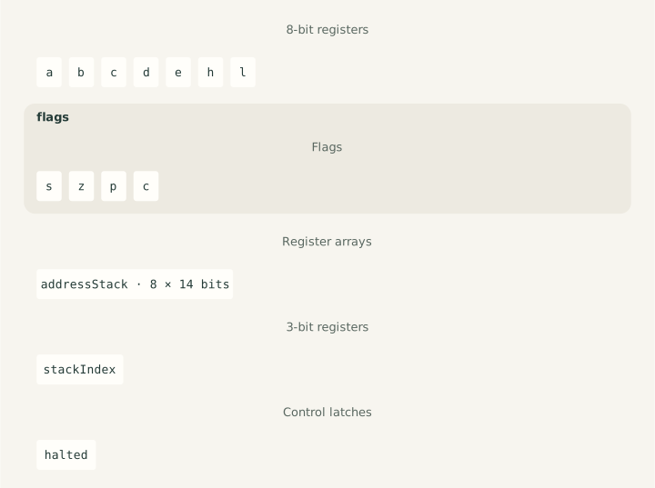
The seven byte registers, four flags, eight address registers, address-register selector, and stopped latch below are the complete stored state of this model. These declarations generate the schema used by construction, snapshots, machine parsing, and instruction validation, together with its TypeScript stored-state type. They declare storage and constraints, not initial or reset values.
Register and flag fields use lowercase names in TypeScript. Architectural flags
live in a separate flags group, so register C and flag C are distinct.
Machine definitions use uppercase register and flag names. The explicit mappings
retain addressStack, stackIndex, and halted for the internal control state.
There is no RAM stack pointer, stack-depth counter, interrupt-enable latch,
auxiliary carry, or overflow flag.
cpu "8008"
state {
  register A: 8
  register B: 8
  register C: 8
  register D: 8
  register E: 8
  register H: 8
  register L: 8
  flag S
  flag Z
  flag P
  flag C
  array ADDRESS: 14[8] = addressStack
  register SELECTOR: 3 = stackIndex
  latch STOPPED = halted
}
Register views
The selected address register is the PC. Read its selector, then that physical slot; inspecting PC never advances it. H:L is the raw sixteen-bit concatenation of the H and L byte registers, including H's upper two bits. Memory addressing still masks that pair to fourteen bits at the point of a memory access. Neither view has separate storage, and both observe the current stored values.
view PC "selected program counter": 14 {
  slot = register SELECTOR
  address = array ADDRESS[slot]
  return address
}
view HL "raw H:L pair": 16 {
  high = register H
  low = register L
  return concat(high, low)
}
The ordinary fetcher supplies a sixteen-bit next address. Truncate it to fourteen bits, read the current selector, and replace only the selected address register. This includes wrapping from $3FFF to $0000; the other seven slots stay intact. Instruction bodies retain their explicit target and selector writes, while interrupt-supplied bytes do not call this action.
action setPC "set the selected program counter" (address: 16) {
  target = truncate(address, 14)
  slot = register SELECTOR
  ADDRESS[slot] <- target
}
Reset
The 8008 has no dedicated reset input. Its documented power-on sequence clears
its internal memories and leaves it stopped; an interrupt starts execution.
reset() models that settled clearing-and-stop result at an instruction boundary.
Selecting slot zero and preserving unspecified flags are deterministic model
policies. No power transition, clock sequence, forced instruction, or interrupt
is simulated, and this operation is distinct from the RST instruction.
Reset models settled power-on state. Clear the seven byte registers and all
eight address registers, select slot zero, and enter STOPPED. The startup
reference does not specify flag values; this model preserves them by omitting
flag reads and writes. ADDRESS[] writes the same value to every physical slot
without reading its previous contents. Repeating reset produces the same state.
RAM and ports are untouched. The shared runtime guards the execution boundary
and records detached before/after snapshots around this action.
action reset "settled power-on reset" {
  A <- u8($00)
  B <- u8($00)
  C <- u8($00)
  D <- u8($00)
  E <- u8($00)
  H <- u8($00)
  L <- u8($00)
  ADDRESS[] <- u14($0000)
  SELECTOR <- u3(0)
  STOPPED <- 1
}
The reset record contains independent before and after snapshots and an
empty, memory-only access list, with no instruction or step outcome. After reset,
interrupt() can start the CPU with an externally supplied instruction.
Example factories instead initialize halted = false; creating a new example
restores its initial state and fresh RAM. Construction never implies power-on.
Execution and interrupt acceptance
An interrupt is an unconditional offer of an instruction. After validating the host's acknowledgement callback, release STOPPED before requesting its first byte. No flags or address registers change during acceptance. A later invalid byte, undefined opcode, or device failure retains this release.
action resume "accept an external instruction" {
  STOPPED <- 0
}
Ordinary execution uses a flat fourteen-bit RAM address space and the selected
PC. A stopped step makes no access. Read one opcode byte; advance PC only when
that byte selects a documented instruction. Each later operand fetch reads the
live PC, then advances it after a successful read. Counter arithmetic supplies
a sixteen-bit next address to setPC, whose narrowing gives the native wrap.
Word operands are low byte first. There is no additional retirement action.
Interrupt execution obtains every instruction byte from acknowledgement, including immediate and address operands, and preserves PC during those fetches. Data-memory and port accesses still use their ordinary connections. The same opcode families execute both ways; supplied HLT can stop the CPU again. An undefined supplied byte retains acceptance effects and fetches no more bytes. Thrown failures propagate, keeping completed effects and returning no record.
execution {
  memory 14
  counter PC write setPC
  stopped STOPPED
  word little
  opcode advance on dispatch
  operand advance after read
  failure retain
  reset action reset
  retire none
  interrupt {
    accept always with resume
    bytes acknowledge
    counter preserve
    unknown retain
  }
}
The shared runtime records completed accesses in order and returns detached before/after snapshots. Unsupported instructions report the fetched byte; already stopped steps report no instruction. A common guard rejects nested step, reset, and interrupt calls, while allowing snapshots in callbacks, and releases after success or failure. These services execute the declared policies.
Instruction steps
step() returns a Cpu8008StepRecord with independent before and after
snapshots, the instruction address and fetched bytes, ordered byte accesses,
and an outcome of executed, halted, or unsupported. Only unsupported
records have reason: "opcode". An already halted step has instruction: null,
no accesses, and unchanged state.
Data reads are separate from instruction bytes and do not advance PC. Stores never read the destination; writes are recorded even if the value is unchanged. Recorded instruction bytes survive stores over their original RAM locations; subsequent instructions read current RAM. All records own their snapshots and access entries, so later CPU or device activity cannot change earlier records.
The six undefined bytes (22, 2A, 32, 38, 39, 3A) read only the
opcode and preserve all state and RAM. Repeating the attempt repeats that read.
Leaving PC unchanged despite fetching the byte is an explicit model policy.
All three HLT encodings (00, 01, FF) advance PC once before stopping
ordinary execution; an external interrupt can release STOPPED.
External interrupt delivery
interrupt(acknowledge: () => number) offers an instruction at the current
boundary. The 8008 has no interrupt mask, enable delay, automatic flag save,
or automatic call. The caller owns request qualification and scheduling; no
request queue or device connection is added to snapshot state. A new offer
can be accepted at the very next boundary.
The callback supplies the opcode and each immediate or address byte exactly
once; every result must be an integer in 00–FF. None advances PC. Data
accesses still use RAM through H:L or the connected ports, and target addresses
remain low-byte first with the high two bits ignored. The instruction bodies
below therefore have these effects when supplied externally:
| Supplied instruction | Effect on control flow |
|---|---|
| RST / taken CAL | Leave the interrupted PC in its slot, select the next slot, and load the target |
| JMP / taken conditional jump | Replace the selected PC |
| RET / taken conditional return | Select the preceding slot without incrementing the outgoing one |
| Untaken conditional transfer | Preserve every slot; jump/call still consume both supplied address bytes |
| LAA or another non-branch instruction | Resume ordinary RAM execution at the unchanged PC |
| HLT | Reenter STOPPED with no PC increment |
An ordinary HLT has already advanced PC, so a supplied RST/CAL preserves the address after that HLT. Calls retain their eight-slot wrap and overwrite behavior. Flags and registers change only as specified by the instruction.
Cpu8008InterruptRecord contains detached before/after snapshots,
instruction: { source: "interrupt", bytes }, and ordered accesses. It has
no RAM instruction address. Acknowledgements use { kind: "acknowledge", value };
data-memory and port transfers retain their ordinary shapes. Outcomes are
executed, halted, or unsupported with reason: "opcode"; there is no masked
or ignored outcome. An undefined byte is acknowledged and rejected after
releasing STOPPED, with no further effect. Ordinary step() instead preserves
all state when rejecting an opcode.
The November 1973 manual, printed pages 18–20 and Figure 5, describes PC suppression and supplied RST/CALL saving the interrupted PC. Its startup examples include LAA at address zero, executed first during the interrupt and then again by ordinary execution. The Intellec 8 Reference Manual, printed pages 18–19, distinguishes CPU acceptance from the peripheral logic supplying a multi-byte instruction. The callback models that external source, without electrical synchronization or multiplexed bus states.
Failure boundaries
A missing or non-callable interrupt callback throws TypeError before
acceptance. An invalid supplied byte throws RangeError; callback, RAM, and
device errors propagate. Failures return no record and retain completed
effects, including STOPPED release, without rollback or implicit retry.
Callbacks may inspect snapshots, but nested step(), reset(), or interrupt()
calls throw before changing CPU state. The execution guard clears after every
failure, allowing a later boundary call.
Public interface
The model is exposed as Cpu8008. Construction takes RAM, initial stored state,
and an optional byte-port connection. It checks RAM before reading initial
state, then validates and copies every stored field, including the address
registers and flags. Caller-owned arrays may be readonly; internal storage is
mutable. The generated Cpu8008State and Cpu8008StoredState types express
that distinction, with Cpu8008AddressStack and Cpu8008Flags aliases derived
from the corresponding stored fields.
Memory uses the byte-connection contract, with RAM as the usual connection.
new Cpu8008(ram, initialState, ports?) requires a 16 KiB byte-memory address space. Numeric
state violations throw RangeError; malformed address arrays and non-Boolean
flags or latches throw TypeError. Sparse address arrays fail numeric
validation. Each declared input field and array slot is read once, including
non-enumerable properties. Extra metadata and derived views are ignored.
Construction neither resets nor executes, and makes no RAM or port accesses.
Snapshots contain a detached copy of all stored state plus the two views below.
Their fields, nested flags, and address registers are readonly to callers.
pc exposes the selected address register; hl exposes the complete H:L pair,
including its upper two bits. Reading a snapshot never accesses RAM or ports.
interface Cpu8008 "Instruction-level Intel 8008 with native port selectors and 14-bit addresses." {
  snapshot pc = PC
  snapshot hl = HL
}
The generated class supplies snapshot(), reset(), step(), and
interrupt(acknowledge), together with their concrete state and result types.
Their behavior follows the execution contract above. The public module, state
types, instruction catalogue, and execution bindings are all generated; this
specification is the sole processor-specific implementation source.
A snapshot can initialize a fresh CPU. Its recursively readonly public type does not freeze the underlying JavaScript objects; bypassing that typing still cannot change the CPU or another snapshot. The CPU retains no record history. Reconstruction reconnects any external devices separately, as described under port input and output.
The build discovers this specification and registers the model from cpu "8008".
Machine parsing uses its generated schema and caller-state types. memory 14
sets the required RAM size to $4000 bytes; the fourteen-bit public PC view sets
completion addresses to $0000–$3FFF. The same generated entry point serves flat
and composed machines. No separate model registration or RAM-size rule is
maintained in TypeScript.
Seven registers and one memory operand
A, B, C, D, E, H, and L each hold a complete byte. Transfers do not read or write the flags, the selected address-stack slot, its selector, or the halted latch.
The eighth operand, M, means the memory byte addressed by H:L. Concatenating H
and L produces sixteen bits, but the 8008 has fourteen address bits. Masking
with $3FFF makes the upper two H bits irrelevant to addressing while retaining
them in the register itself. Thus $3FFF, $7FFF, $BFFF, and $FFFF all
address the same byte; a transfer from H still reads all eight bits of H.
source throughHL "memory address through low 14 bits of HL": 16 {
  high = register H
  low = register L
  return and(concat(high, low), u16($3FFF))
}
Each three-bit selector uses the order A/B/C/D/E/H/L/M. A register entry can be read or written directly. A memory entry resolves its address at the time of the operand read or write; selecting M does not eagerly read H or L.
operands bytes {
  000 "A" = register A
  001 "B" = register B
  010 "C" = register C
  011 "D" = register D
  100 "E" = register E
  101 "H" = register H
  110 "L" = register L
  111 "M" = memory throughHL
}
Register and memory transfers
The November 1973 manual, printed pages 8–11, gives the selectors, load forms, and flag rules. The transfer matrix contains 49 register copies, seven memory reads, and seven memory writes; immediate loads add eight forms. Loading H or L from memory reads through the original H:L before replacing the destination. A register self-transfer reads only its opcode from RAM.
The encoding is 11 ddd sss: ddd selects the destination and sss the source.
Intel names a transfer Lds, placing the destination before the source: LBA
loads B from A, LAM loads A from memory, and LMA stores A to memory. The name
template below uses those selected operand labels.
The 11 111 111 slot belongs to HLT, so it is explicitly excluded.
Capture the selected source byte before writing the destination, including self-transfers and unchanged writes. For M, read H then L at the access point and mask only the address to $3FFF. Stores resolve it after capturing the source, even when storing H or L, and never read the destination. Do not access flags or control state. A failed source read prevents writeback.
family transfer "11 ddd sss" for d in bytes, s in bytes named "L{d}{s}" except "11 111 111" {
  result = operand s
  operand d <- result
}
Immediate loads
The encoding 00 ddd 110 selects the destination in the same way, followed by
one immediate byte. All eight destinations exist, including M. Fetching advances
the selected address register in ordinary execution, while interrupt-supplied
bytes follow the CPU's existing supplied-stream contract.
Fetch the immediate byte before touching the destination. For M, then read H and L and mask only the address to $3FFF. Never read destination memory; write once, even if unchanged. Preserve flags. A failed fetch prevents destination effects.
family immediate "00 ddd 110" for d in bytes named "L{d}I n" {
  result = fetch
  operand d <- result
}
Arithmetic operands and flags
The November 1973 manual, printed pages 11–12, defines the accumulator operations and flags. H and L contribute all eight bits as operands. A memory operand makes a separate data read even when it aliases the opcode; it neither writes RAM nor increments PC. Other data registers and inactive address slots remain unchanged.
The accumulator A supplies the left operand. The right operand is a selected register, M through the same masked H:L address, or the next instruction byte. Read that source completely before reading incoming carry or A. Even an instruction using A as its source reads A twice, at these separate points. Immediate fetching retains the ordinary/supplied-stream rule described above.
source immediateByte "immediate byte": 8 {
  byte = fetch
  return byte
}
Register C and carry flag C are distinct storage locations. register C and
flag C distinguish their reads; flag writes belong to explicit policies.
S reports bit 7 of a byte result, Z reports zero, and P reports even parity,
including zero. Adjustments preserve carry without reading it; accumulator
arithmetic also replaces carry. Each policy's listed flags change in one stage.
policy SZP "8008 result S/Z/P" (result: 8) {
  S = negative(result)
  Z = zero(result)
  P = evenParity(result)
}
policy ALU "8008 result S/Z/P/C" (result: 8, carry: flag) {
  S = negative(result)
  Z = zero(result)
  P = evenParity(result)
  C = carry
}
Eight accumulator operations
Both encodings select the same operation: 10 ooo sss uses A/B/C/D/E/H/L/M,
while 00 ooo 100 fetches an immediate byte. Each family below lists both
encodings and supplies their shared body once. The immediate encoding binds
s to the instruction-byte source instead of a three-bit operand selector.
| ooo | Register/memory | Immediate | Result |
|---|---|---|---|
| 000 | ADs | ADI | A plus source |
| 001 | ACs | ACI | A plus source plus C |
| 010 | SUs | SUI | A minus source |
| 011 | SBs | SBI | A minus source minus C |
| 100 | NDs | NDI | A AND source |
| 101 | XRs | XRI | A XOR source |
| 110 | ORs | ORI | A OR source |
| 111 | CPs | CPI | Compare A with source |
Addition and subtraction wrap to eight bits. Carry reports an unsigned total
above FF; borrow reports a subtraction below zero. The 8008 uses C directly
as borrow on subtraction. It has no overflow or half-carry flag. The carry
and borrow expressions use captured operands, never a later state read.
AD
Read the source, then A without reading incoming flags. Add with byte wraparound; set S/Z and even parity P from the result, and C from unsigned carry, before writing A. A failed source read prevents arithmetic and writeback.
family AD {
  encoding "10 000 sss" for s in bytes.read named "AD{s}"
  encoding "00 000 100" with s = immediateByte named "ADI byte"
  right = source s
  left = register A
  result = add(left, right)
  apply ALU(result, carry(left, right))
  A <- result
}
AC
Read the source, capture incoming C, then read A. Add both bytes and that captured carry with byte wraparound. Apply S/Z/P and unsigned carry before writing A. A failed source read prevents carry reads and writeback.
family AC {
  encoding "10 001 sss" for s in bytes.read named "AC{s}"
  encoding "00 001 100" with s = immediateByte named "ACI byte"
  right = source s
  carry = flag C
  left = register A
  result = add(left, right, carry)
  apply ALU(result, carry(left, right, carry))
  A <- result
}
SU
Read the source, then A without reading incoming flags. Subtract with byte wraparound; set S/Z/P from the result and C from unsigned borrow before writing A. A failed source read prevents arithmetic and writeback.
family SU {
  encoding "10 010 sss" for s in bytes.read named "SU{s}"
  encoding "00 010 100" with s = immediateByte named "SUI byte"
  right = source s
  left = register A
  result = subtract(left, right)
  apply ALU(result, borrow(left, right))
  A <- result
}
SB
Read the source, capture incoming C, then read A. Subtract the source and that captured borrow with byte wraparound. Apply S/Z/P and unsigned borrow before writing A. A failed source read prevents carry reads and writeback.
family SB {
  encoding "10 011 sss" for s in bytes.read named "SB{s}"
  encoding "00 011 100" with s = immediateByte named "SBI byte"
  right = source s
  carry = flag C
  left = register A
  result = subtract(left, right, carry)
  apply ALU(result, borrow(left, right, carry))
  A <- result
}
ND
Read the source before A and compute their bitwise AND. Set S/Z/P from the result and clear C before writing A, without reading incoming flags. A failed source read prevents calculation and writeback.
family ND {
  encoding "10 100 sss" for s in bytes.read named "ND{s}"
  encoding "00 100 100" with s = immediateByte named "NDI byte"
  right = source s
  left = register A
  result = and(left, right)
  apply ALU(result, 0)
  A <- result
}
XR
Read the source before A and compute their bitwise XOR. Set S/Z/P from the result and clear C before writing A, without reading incoming flags. A failed source read prevents calculation and writeback.
family XR {
  encoding "10 101 sss" for s in bytes.read named "XR{s}"
  encoding "00 101 100" with s = immediateByte named "XRI byte"
  right = source s
  left = register A
  result = xor(left, right)
  apply ALU(result, 0)
  A <- result
}
OR
Read the source before A and compute their bitwise OR. Set S/Z/P from the result and clear C before writing A, without reading incoming flags. A failed source read prevents calculation and writeback.
family OR {
  encoding "10 110 sss" for s in bytes.read named "OR{s}"
  encoding "00 110 100" with s = immediateByte named "ORI byte"
  right = source s
  left = register A
  result = or(left, right)
  apply ALU(result, 0)
  A <- result
}
CP
Read the source before A, without reading incoming flags. Compute the wrapped byte subtraction only to set S/Z/P and unsigned borrow C. Leave A unchanged without writing it. A failed source read prevents every flag update.
family CP {
  encoding "10 111 sss" for s in bytes.read named "CP{s}"
  encoding "00 111 100" with s = immediateByte named "CPI byte"
  right = source s
  left = register A
  result = subtract(left, right)
  apply ALU(result, borrow(left, right))
}
Increment and decrement
The encoding 00 rrr 00d adjusts B/C/D/E/H/L, with d=0 for increment and d=1
for decrement. A has no adjustment: its two slots are HLT. M has no adjustment
either, and its two slots remain undefined. The exclusions make both exceptions
visible beside each pattern.
H remains a full byte, and adjusting L never carries into H. Adjustments and rotations follow the November 1973 manual, printed pages 11 and 13.
Read the selected register once, add one with byte wraparound, and apply S/Z/P before writing the register. Preserve C without reading it. No instruction operand, data memory, or control state is accessed.
family IN "00 rrr 000" for r in bytes named "IN{r}" except "00 000 000", "00 111 000" {
  original = operand r
  result = add(original, u8($01))
  apply SZP(result)
  operand r <- result
}
Read the selected register once, subtract one with byte wraparound, and apply S/Z/P before writing the register. Preserve C without reading it. No instruction operand, data memory, or control state is accessed.
family DC "00 rrr 001" for r in bytes named "DC{r}" except "00 000 001", "00 111 001" {
  original = operand r
  result = subtract(original, u8($01))
  apply SZP(result)
  operand r <- result
}
Accumulator rotations
The four encodings are 00 0td 010: t=0 rotates the outgoing bit back into A,
while t=1 inserts incoming C; d=0 shifts left and d=1 shifts right. The outgoing
bit always replaces C, after writing A. S/Z/P retain their previous values even
if the new accumulator is zero or has a different sign or parity.
policy rotateCarry "8008 rotate carry" (carry: flag) {
  C = carry
}
Capture A and rotate left, inserting its original bit 7 into bit 0. Write A before replacing C with that outgoing bit. Preserve S/Z/P without reading them; make no operand fetch or data-memory access.
family RLC "00 000 010" {
  original = register A
  result = shiftLeft(original, negative(original))
  A <- result
  apply rotateCarry(negative(original))
}
Capture A and rotate right, inserting its original bit 0 into bit 7. Write A before replacing C with that outgoing bit. Preserve S/Z/P without reading them; make no operand fetch or data-memory access.
family RRC "00 001 010" {
  original = register A
  result = shiftRight(original, lowBit(original))
  A <- result
  apply rotateCarry(lowBit(original))
}
Capture A before reading incoming C, then rotate left with the captured carry entering bit 0. Write A before replacing C with original bit 7. Preserve S/Z/P; make no operand fetch or data-memory access.
family RAL "00 010 010" {
  original = register A
  carry = flag C
  result = shiftLeft(original, carry)
  A <- result
  apply rotateCarry(negative(original))
}
Capture A before reading incoming C, then rotate right with the captured carry entering bit 7. Write A before replacing C with original bit 0. Preserve S/Z/P; make no operand fetch or data-memory access.
family RAR "00 011 010" {
  original = register A
  carry = flag C
  result = shiftRight(original, carry)
  A <- result
  apply rotateCarry(lowBit(original))
}
Eight address registers
The 8008 has eight physical fourteen-bit address registers. A three-bit selector chooses the current PC; the other seven slots can retain return addresses. A call advances the selector modulo eight, then writes its target to the newly selected slot. A return only moves the selector back. Neither operation copies addresses or accesses a stack in RAM. An eighth nested call overwrites the oldest return address.
Numbering slots by incrementing for calls and decrementing for returns is a model convention. Extra returns continue around the ring without a depth check or fault, and no slot is cleared on return. An ordinary RET advances its outgoing slot for the opcode fetch before changing the selector; that advanced value remains in the inactive slot. Intel's November 1972 revision, Appendix II, describes these increments before stack selection changes.
The November 1973 manual, printed pages 13–14, defines the control encodings and both conditional paths. Every target fetch retains the entire high byte in its record even though addressing ignores the high two bits. Conditional jumps and calls fetch all three bytes on either path; an untaken call preserves all inactive slots. Control instructions preserve data registers, flags, and RAM, with no destination prefetch.
The specification calls these locations ADDRESS and SELECTOR. They refer to the
stored fields addressStack and stackIndex declared above; SELECTOR is an
internal selection register, not an additional software-visible byte register.
Ordinary opcode and operand fetching advances the selected address register with fourteen-bit wraparound. Interrupt-supplied bytes leave it unchanged. Those rules remain in the CPU boundary; the bodies below only perform the instruction's explicit target and selector changes.
Targets arrive low byte first. Fetch both bytes before reading any condition or selector, concatenate them, and discard the high two bits. A failed second fetch retains the first fetch's effects and prevents the later state changes.
source targetAddress "14-bit target, low byte first": 14 {
  low = fetch
  high = fetch
  return truncate(concat(high, low), 14)
}
Conditional control flow
The three-bit condition field is vff: v=0 requires a clear flag and v=1 a set
flag; ff selects C/Z/S/P. Intel's mnemonic suffixes combine F/T with that flag
name: JFC jumps if carry is clear, CTP calls if parity is set, and RFS returns
if sign is clear. Selecting a condition does not read flags. when test c
reads exactly that selected flag where the statement appears, then executes
its block only when the required value matches.
conditions branches {
  000 "FC" = flag C = 0
  001 "FZ" = flag Z = 0
  010 "FS" = flag S = 0
  011 "FP" = flag P = 0
  100 "TC" = flag C = 1
  101 "TZ" = flag Z = 1
  110 "TS" = flag S = 1
  111 "TP" = flag P = 1
}
Conditional jumps use 01 ccc 000. Fetch and narrow the complete target before
testing the selected flag. Only a taken jump reads SELECTOR and writes the
selected address register. Do not read target memory or change flags, SELECTOR,
or STOPPED; an untaken jump has only its instruction-fetch effects.
family conditionalJump "01 ccc 000" for c in branches named "J{c}" {
  target = source targetAddress
  when test c {
    slot = register SELECTOR
    ADDRESS[slot] <- target
  }
}
Conditional calls use 01 ccc 010. Fetch and narrow the complete target before
testing the selected flag. Only a taken call reads SELECTOR, advances it modulo
eight, and writes the target into that new physical slot. Preserve all other
slots, flags, and STOPPED. An untaken call never accesses the selector or array.
family conditionalCall "01 ccc 010" for c in branches named "C{c}" {
  target = source targetAddress
  when test c {
    slot = register SELECTOR
    next = truncate(add(extend(slot, 8), u8($01)), 3)
    SELECTOR <- next
    ADDRESS[next] <- target
  }
}
Conditional returns use 00 ccc 011. Test the selected flag before reading
SELECTOR. Only a taken return decrements it modulo eight. Keep every physical
address register unchanged; do not read a return address, fetch an operand,
or access data memory. Preserve flags and STOPPED. Ordinary opcode fetching
advances the current slot; externally supplied bytes leave it unchanged.
family conditionalReturn "00 ccc 011" for c in branches named "R{c}" {
  when test c {
    slot = register SELECTOR
    next = truncate(subtract(extend(slot, 8), u8($01)), 3)
    SELECTOR <- next
  }
}
Unconditional jumps, calls, and returns
The unconditional forms ignore their middle three bits: JMP is 01 xxx 100,
CAL is 01 xxx 110, and RET is 00 xxx 111. Each pattern therefore names eight
documented opcode aliases. Unlike conditional forms, these instructions never
read flags.
Fetch both target bytes, low first, and narrow to fourteen bits. Then read SELECTOR and replace only its selected address register. JMP leaves all other slots, the selector, flags, and STOPPED unchanged, without reading target memory.
family JMP "01 xxx 100" {
  target = source targetAddress
  slot = register SELECTOR
  ADDRESS[slot] <- target
}
Fetch and narrow the complete target, then advance SELECTOR modulo eight before writing that target into the new slot. CAL leaves the caller's slot holding its post-fetch address, or its unchanged address for supplied bytes. Preserve other slots, flags, and STOPPED; perform no data-memory access.
family CAL "01 xxx 110" {
  target = source targetAddress
  slot = register SELECTOR
  next = truncate(add(extend(slot, 8), u8($01)), 3)
  SELECTOR <- next
  ADDRESS[next] <- target
}
Read SELECTOR and decrement it modulo eight. RET leaves all eight physical address registers, flags, and STOPPED unchanged. It neither reads a return address nor fetches an operand, and performs no data-memory access.
family RET "00 xxx 111" {
  slot = register SELECTOR
  next = truncate(subtract(extend(slot, 8), u8($01)), 3)
  SELECTOR <- next
}
Restarts and halts
The restart pattern is 00 vvv 101. Its three-bit field selects one of eight
fixed fourteen-bit target addresses. The catalogue distinguishes the encoded
bits from their values and native hexadecimal labels.
codes vectors: 14 {
  000 "00" = $00
  001 "08" = $08
  010 "10" = $10
  011 "18" = $18
  100 "20" = $20
  101 "28" = $28
  110 "30" = $30
  111 "38" = $38
}
Capture the encoded restart target without fetching an operand. Read SELECTOR, advance it modulo eight, then write the target into the new slot, just as for CAL. Preserve all other slots, flags, and STOPPED. Ordinary opcode fetching has already advanced the caller's slot; supplied opcodes have left it unchanged.
family RST "00 vvv 101" for v in vectors {
  target = operand v
  slot = register SELECTOR
  next = truncate(add(extend(slot, 8), u8($01)), 3)
  SELECTOR <- next
  ADDRESS[next] <- target
}
STOPPED refers to the model's halted control latch. It is distinct from the
architectural flags and is not changed by the preceding control instructions.
HLT occupies 00 000 00x and 11 111 111: three documented encodings. Set
STOPPED without reading registers, flags, or the old latch. Opcode fetching
alone determines whether the selected address register has advanced. A stopped
CPU waits for the existing external interrupt boundary to supply an instruction.
family HLT {
  encoding "00 000 00x"
  encoding "11 111 111"
  STOPPED <- 1
}
Port input and output
The November 1973 manual, printed page 14, defines the transfers;
page 62 confirms the assembler's port numbering: input 000–007 and output
010–037 in octal. INP opcodes are 41, 43, …, 4F; OUT opcodes are
51, 53, …, 7F. Output selectors retain their encoded values.
Port instructions use 01 ppppp 1; the five-bit field is the entire port
selector, with no immediate byte. Ports 0..7 are inputs, and ports 8..31 are
outputs. The catalogue widens the encoded values to the common sixteen-bit
port interface without changing those native selector numbers. Labels retain
the decimal port numbers used by the instruction names.
codes ports: 16 {
  00000 "0"
  00001 "1"
  00010 "2"
  00011 "3"
  00100 "4"
  00101 "5"
  00110 "6"
  00111 "7"
  01000 "8"
  01001 "9"
  01010 "10"
  01011 "11"
  01100 "12"
  01101 "13"
  01110 "14"
  01111 "15"
  10000 "16"
  10001 "17"
  10010 "18"
  10011 "19"
  10100 "20"
  10101 "21"
  10110 "22"
  10111 "23"
  11000 "24"
  11001 "25"
  11010 "26"
  11011 "27"
  11100 "28"
  11101 "29"
  11110 "30"
  11111 "31"
}
Capture the encoded input selector, read one byte from that port, and replace A only after the read succeeds. Never read old A or any flag. Preserve all other registers and control state; fetch no operand and access no data memory.
family INP "01 ppppp 1" for p in ports except "01 01xxx 1", "01 1xxxx 1" {
  selector = operand p
  result = port(selector)
  A <- result
}
Capture the encoded output selector, then A, and write that byte once to the port. Do not reread A during the callback or change registers, flags, or control state. Fetch no operand and access no data memory. A failed callback retains any effects the device has already performed.
family OUT "01 ppppp 1" for p in ports except "01 00xxx 1" {
  selector = operand p
  contents = register A
  port(selector) <- contents
}
These families complete the 250 documented opcode forms. The six undefined
encodings (22, 2A, 32, 38, 39, and 3A) stay absent. The execution
contract selects these same families for ordinary and interrupt-supplied bytes;
shared runtime services enforce guarding and assemble records.
Device connection and records
The optional third constructor argument is the shared
BytePorts connection: readPort(port): number and
writePort(port, value): void. Input must return an unsigned byte. The CPU
retains the connection and calls it during execution; the caller owns device
state, which is neither snapshotted nor reset. Reconstructing a CPU requires
reconnecting its device. Construction, inspection, reset, undefined instructions,
and already halted steps make no port calls. RAM-only programs need no connection.
Cpu8008Access uses { kind: "read" | "write", address, value } for memory and
{ kind: "input" | "output", port, value } for ports. A successful ordinary INP
or OUT records its opcode read followed by the port transfer, including unchanged
inputs and repeated outputs. Port transfers do not become instruction bytes.
A missing connection, invalid input byte, or device error throws a host error and returns no instruction record. The completed opcode fetch remains: during ordinary execution PC has advanced, while A, flags, and inactive slots remain unchanged. Device side effects are not rolled back. The common failure boundary also applies to port callbacks.
References
For historical background, Intel's account establishes the product's origins, and the 2006 oral-history panel records the designers' recollections. Contemporary manuals establish the technical contract; dated lab notes and contemporary publications ground the system examples. Historical context explains design choices without making a later recollection part of the executable hardware contract.
The hardware reference is Intel's 8008 User's Manual, April 1972 (searchable copy), especially Basic Functional Blocks, Basic Instruction Set, Start-Up of the 8008, and Appendix I's functional definitions. The November 1972 revision, Appendix II, adds the PC-increment details. Instruction sections above cite printed pages in the November 1973 manual; the Intellec 8 manual clarifies the external interrupt source. The tutorial's earlier teaching model uses 8080 encodings; this specification follows Intel's hardware 8008 encodings.
Checks and limits
CPU tests · Interrupt program test · Public type checks
CPU tests check every byte pair and both incoming carry values for all eight immediate ALU operations against independent decimal arithmetic, logical truth tables, and binary-digit counts. Every register/memory and immediate encoding also checks all operand bytes and incoming flag patterns at accumulator boundaries, including A as its own source. Memory ALU checks cover H's four address aliases, boundaries, and code overlaps, with no writes.
Other tests check all load bytes and flag patterns, all H:L combinations, every PC, and each address-stack selector. They compare complete records and actual RAM accesses, including unchanged-value writes, self-modified code, unsupported attempts, all three HLT encodings, reset, and detached records.
Transfer checks cover every matrix encoding, byte value, and incoming flag pattern, with all eight PC slots and wrapped opcode fetches. Memory cases also check the four aliases formed by H's top bits, address-space boundaries, instruction overlap, and loads into H and L. LAM and LMA each cover every H:L combination. LMI covers every byte and flag pattern, wrapped operand fetches, and aliased writes over its own opcode or operand. Further checks verify that memory loads see RAM edits and the pointer left by a preceding load.
Control-flow checks cover all documented aliases, every encoded destination including ignored high bits, every selector and flag pattern, wrapped fetches, eight nested calls, overwritten return addresses, and unbalanced returns. Conditional checks cover all 24 encodings and all 16 flag patterns in every slot. Jump/call cases include four address aliases, byte-boundary wrapping, self-targets, and destinations overlapping instruction bytes on both paths. Return cases check retained outgoing slots, boundary destinations, and equal PC values in different slots. A repeated conditional jump also checks current flags, edited address bytes, and detached records.
Adjustment and rotation tests cover all 256 operand values and all 16 incoming flag patterns, checking full records, preserved registers/flags, and actual RAM calls. RST tests cover every vector from every PC, all stack selectors and flag patterns, wrapped fetches, overlapping targets, returns, and eight nested restarts overwriting the oldest return address. An opcode audit exercises all 250 documented forms and rejects exactly the six undefined bytes. Port tests check every selector and byte, preserved flags and address slots, wrapped fetches, live device state, ordered transfers, detached records, callback reentrancy, and connection failures. A combined INP/CAL/ADI/OUT/RET/HLT program checks bounded running and snapshot restoration across a wrapped call.
Interrupt tests check every RST vector, stack selector, and flag pattern at boundary PCs; all jump/call/return aliases; both paths of every condition; one-, two-, and three-byte supplied instructions; memory and port access order; STOPPED release and reentry; undefined bytes; and callback validation, failure, reentrancy, and record ownership. The combined interrupt program starts after reset, initializes RAM through a supplied RST, halts, services a supplied CAL, returns, and resumes arithmetic/output. Reconstructing the CPU at each boundary with its snapshot and reconnected device preserves the trace.
The generated examples check both factories, whole memory images, complete traces, bounded running, caller completion, reset, and fresh restart. The nested-call trace also checks inactive slot contents across returns. The ALU example checks resumption with a pending borrow and preservation of comparison flags through the output stores and halt. The control-flow trace checks both paths of each conditional family, a skipped failure path, and resumption between an untaken RFZ and a taken RTZ. The carry trace checks RST/RET, both RFZ paths, pointer page crossing, and resumption with carry pending between two RAM bytes. Parser and generator tests cover address lists, ranges, RAM size, diagnostics, and declaration order. Type checks preserve concrete CPU and runner records.
Memory-mapped devices, cycle timing, ongoing internal refresh, dummy accesses, and pin activity remain outside this model. This includes READY waits and the multiplexed presentation of A and flags during input cycles. Opcode completion does not imply complete processor emulation or cycle accuracy.
Example programs
The example specifications retain their programs, traces, and acceptance criteria:
- Arithmetic: load, add, and store through H:L.
- ALU: propagate carry and borrow, combine bits, and preserve comparison flags through stores and halt.
- Nested calls: follow the circular address registers and retained outgoing slots.
- Transfers: follow a byte through registers and RAM, then change the pointer by loading H from memory.
- Control flow: use comparisons and arithmetic flags in a loop with conditional calls and returns.
- Carry and restart: preserve carry across pointer and count adjustments between rotations.