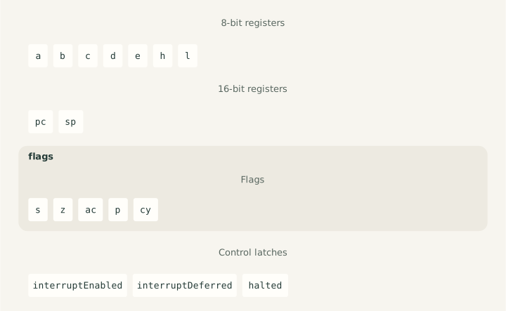
This specification is the complete implementation source and guide for Dromaios's instruction-level Intel 8080. Its formal blocks define every documented instruction, stored state, register views, reset, normal and interrupt execution, and the public API. Shared TypeScript compiles those rules and supplies runtime services; there is no handwritten 8080 implementation or separate model document. The coverage report records current fidelity and migration measures.
History · Physical operation · Architecture · Worked execution · Formal model · Checks and examples · References
Historical background
Intel introduced the 8080 in 1974, two years after the 8008. Federico Faggin, its lead designer, responded to customers who found the earlier processor too restrictive for larger programs. Intel's fiftieth-anniversary account describes a shift from processors conceived for particular customers to a product that other manufacturers could build many kinds of computers around.
The MITS Altair 8800 brought the 8080 into personal computing. Other uses ranged from Hugin cash registers to the arcade games Gun Fight and Space Invaders. These machines shared a processor, but their memory, controls, displays, and software made them different systems. Intel's historical account places those applications alongside the chip's development.
What changed from the 8008?
The 8008 guide introduces the accumulator, six other byte registers, H:L memory addressing, condition flags, and a stack of return addresses. The 8080 retains that broad organization while removing several constraints. Compare the two specifications' formal models:
| Programmer-visible choice | 8008 | 8080 |
|---|---|---|
| Memory address | Fourteen bits: 16 KiB | Sixteen bits: 64 KiB |
| Return addresses | Eight internal address slots, including the active PC | A separate PC and a stack in RAM selected by SP |
| Word operations | H:L supplies a memory address | BC, DE, HL, and SP participate in word transfers and arithmetic |
| Arithmetic flags | Sign, zero, parity, carry | Also auxiliary carry, used in decimal adjustment |
| Port selection | Encoded in the opcode: eight input and twenty-four output ports | A following byte selects one of 256 ports for either direction |
| Interrupt recognition | No instruction-controlled enable flag | DI/EI control acceptance, with a delay after EI |
A RAM stack lets a program choose how much memory to reserve for nested subroutines and saved registers. Its limit becomes the available memory and the program's discipline: the CPU does not check whether the stack has collided with code or data. The larger address space similarly changes what a program can hold, without changing the size of a byte calculation.
The family resemblance does not make the machine code interchangeable. For
example, the 8008's immediate accumulator load starts with $06; the 8080's
MVI A,n starts with $3E. The formal encoding catalogues describe each
processor independently. Intel's 1975 programming manual, chapter 1,
provides the contemporary introduction to the 8080's registers, memory, stack,
and addressing conventions.
The physical chip
Inside the package
Intel's 8080A data sheet, Figures 1–2 and the pin descriptions, shows a 40-pin chip made using an N-channel silicon-gate MOS process. Internal blocks include the register array, accumulator, ALU, decoder, and timing/control logic. Temporary registers, including W and Z, support instruction execution without becoming directly accessible program registers.
The package needs +5 V, +12 V, and −5 V supplies and two external clock phases. Its main signal groups are:
| Signals | Role |
|---|---|
| A0–A15 | Address memory or select an I/O device |
| D0–D7 | Carry data and, at a cycle's start, status information |
| SYNC | Identify the start of a machine cycle |
| DBIN / WR | Coordinate input / active-low output transfers |
| READY / WAIT | Request / acknowledge extra time for a transfer |
| HOLD / HLDA | Request / acknowledge release of the buses |
| INT / INTE | Request an interrupt / expose interrupt enable |
| RESET | Restart instruction fetching at address zero |
| φ1 / φ2 | Supply the two clock phases |
Memory, device selection, clock generation, and bus-control circuitry therefore remain parts of the surrounding computer. A CPU alone is not an Altair.
From a clock to an instruction
The hardware manual, The Processor Cycle and State Transition Sequence, distinguishes a clock state, a machine cycle, and a whole instruction. A typical external transfer proceeds as follows:
| State | Activity |
|---|---|
| T1 | Present an address and a status byte; assert SYNC |
| T2 | Prepare the data transfer and sample READY |
| TW, if needed | Wait until READY permits completion |
| T3 | Read or write the byte |
| T4/T5, when needed | Complete internal work |
External logic latches the status byte to distinguish opcode fetches, data accesses, stack transfers, I/O, and interrupt acknowledgement. It is unrelated to the arithmetic flag byte saved by PUSH PSW. Instructions can need several machine cycles; DAD even needs internal cycles without external transfers. Consequently, counting recorded RAM accesses cannot recover execution time.
The original 8080's maximum clock rate was 2 MHz, according to Intel's history. That is a 0.5-microsecond clock period, not a 0.5-microsecond instruction. Extra states, transfers, and waits make the instruction take longer. Dromaios currently records none of that elapsed time.
Hardware and the instruction model
The diagram and definitions below expose architectural values and ordered
effects. They do not reproduce the temporary registers or electrical signals
used to achieve them. For example, a generated instruction's captured low
and high values explain a word transfer; they do not claim that particular
physical latches hold those values at particular clock edges.
READY waiting, relinquishing the bus through HOLD, and executing HLT are different hardware events. Only HLT has a stored stopped state in this model. The model boundary defines its RAM, port, and interrupt connections; a later timing model would need to describe the other mechanisms.
The programmer's machine
A byte has eight bits and holds $00–$FF; a word has sixteen and holds
$0000–$FFFF. This specification prefixes hexadecimal values with $. Intel's
assembly examples use a trailing H, as in 1234H; both denote the same
number. Binary strings in opcode patterns describe bits, with the most
significant bit on the left.
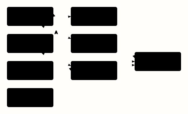
Diagram source
<diagram padding="24" theme="light" background="#fffefa">
  <graph direction="lr" gap="28" row-gap="60">
    <rect id="registers" width="160" height="66">A B C D E H L</rect>
    <rect id="alu" width="160" height="66">Byte arithmetic and logic</rect>
    <rect id="flags" width="160" height="66">S Z AC P CY</rect>
    <rect id="pairs" width="160" height="66">B:C D:E H:L</rect>
    <rect id="memory" width="160" height="66">64 KiB memory</rect>
    <rect id="pc" width="160" height="66">PC: next instruction</rect>
    <rect id="sp" width="160" height="66">SP: stack pointer</rect>
    <rect id="ports" width="160" height="66">256 input/output ports</rect>
  </graph>
  <connect from="registers" to="alu" arrow="both"/>
  <connect from="flags" to="alu" arrow="both"/>
  <connect from="registers" to="pairs"/>
  <connect from="pairs" to="memory"/>
  <connect from="pc" to="memory"/>
  <connect from="sp" to="memory"/>
  <connect from="registers" to="ports" arrow="both" label="A"/>
</diagram>
Registers, pairs, and addresses
| Name | Width | How a program uses it |
|---|---|---|
| A | Byte | Accumulator: the main arithmetic operand/result and the byte transferred by IN/OUT |
| B, C, D, E, H, L | Byte each | Working values, counters, or halves of a word |
| BC, DE, HL | Word each | Views of B:C, D:E, and H:L, with the first register supplying the high byte |
| PC | Word | Address from which the next ordinary instruction byte is fetched |
| SP | Word | Pointer into the RAM stack |
| M | Byte operand | The memory byte at address H:L; it is not another stored register |
For example, H=$12 and L=$34 mean HL=$1234. MOV A,M reads RAM at
$1234; MOV M,A writes there. Changing L to $35 immediately changes
which byte M denotes. There is no separate HL value to keep synchronized.
In Intel syntax, LXI H,1234H names the pair by H, while MVI H,12H names
only its high byte. The word operand catalogue
makes that distinction explicit.
An address and a value can have identical bits but different roles. In
MVI A,80H, $80 is the value to load. In LDA 0080H, $0080 selects
the memory byte to load. In MOV A,M, the address instead comes from H:L.
These are immediate, direct, and register-indirect ways of finding an operand.
Memory contains both instructions and data; there is no type tag on a byte. PC determines which byte is interpreted as an opcode. Its encoding determines whether the next bytes are operands. A jump into an operand would interpret that byte as an opcode instead. Writing over program memory can therefore change later execution.
Words in a byte stream
The 8080 places the low byte of an immediate word or direct address first.
Thus LXI H,1234H is $21 $34 $12, and STA 1234H is $32 $34 $12.
The first byte selects the operation; the next two assemble the word $1234.
Register names H:L still put the high byte first when written on the page.
This difference between written significance and memory order is little-endian
storage, not a reversal of the bits within each byte.
The same memory order appears when SHLD stores H:L: L goes to the selected
address and H to the next. A word in memory occupies two bytes, transferred
through two accesses. At the top of the model's address space, the address
after $FFFF wraps to $0000.
Flags describe an operation
Flags are remembered results of particular instructions. They are not a continuous interpretation of A: loading zero into A does not set Z. The arithmetic policies determine exactly which flags each instruction updates.
| Flag | Meaning for ordinary byte addition | A useful distinction |
|---|---|---|
| S | Result bit 7 is set | Describes the sign bit, not signed overflow |
| Z | Result is zero | May describe a counter or memory result instead of A |
| AC | Carry from bit 3 into bit 4 | Records the low-nibble boundary for decimal adjustment |
| P | Result has an even number of one bits | Measures bit parity, not whether the numeric value is even |
| CY | Carry beyond bit 7 | Supplies carry to ADC; subtraction uses it for borrow |
Consider three additions, with all numbers hexadecimal:
| Calculation | Byte result | S | Z | AC | P | CY |
|---|---|---|---|---|---|---|
$02 + $03 |
$05 |
0 | 0 | 0 | 1 | 0 |
$7F + $01 |
$80 |
1 | 0 | 1 | 0 | 0 |
$FF + $01 |
$00 |
0 | 1 | 1 | 1 | 1 |
$05 has two one bits, although five is odd. Zero has no one bits, which is
also even parity. In the second row, unsigned 127 + 1 fits in a byte, so CY
is clear. Interpreted as signed two's-complement arithmetic, it has overflowed
from 127 to −128; the 8080 has no separate overflow flag to report that fact.
Instruction choice matters when flags carry information between operations. INR and DCR preserve CY, allowing a loop counter to change without destroying a carry being propagated through a multi-byte calculation. DAD changes only CY, and INX/DCX preserve every flag. CMP updates the subtraction flags without replacing A, letting the following conditional instruction inspect a comparison. AC's subtraction and logical-operation rules require particular care; the formal policy discussion distinguishes them from the addition examples above.
DAA gives AC a practical use. In packed binary-coded decimal, each nibble
represents a decimal digit: $09 means nine and $15 means fifteen.
Adding $09 + $06 first gives the binary result $0F; DAA corrects it to
$15. It is a separate instruction after addition, not a persistent decimal
mode. The decimal example
demonstrates correction and carry propagation.
A stack in ordinary memory
SP selects the top occupied byte when the stack holds data. A push makes room by moving toward lower addresses; a pop moves back toward higher addresses. An initially empty stack can start with SP just above its reserved RAM area. The stored state has no stack-length or empty/full field.
CALL saves the address of the next instruction, then redirects PC to a subroutine. RET reloads that saved address. Nested calls work because the most recently saved address is the first one retrieved. A routine must balance its extra PUSH/POP operations before RET, or the return will use the wrong bytes. PUSH PSW saves A and the packed arithmetic flags; it does not save interrupt enable or the rest of the registers.
RST is a compact call to one of eight fixed addresses, $0000, $0008, …,
$0038. These entries can jump to longer routines elsewhere. Its single-byte
encoding also makes RST useful as an instruction supplied by an interrupting
device, as explained in external interrupt delivery.
Reading an opcode pattern
The formal blocks expose repeated fields instead of an unrelated list of
byte values. For instance, $78 is binary 01 111 000: the 01 ddd sss
MOV pattern, with destination A (111) and source B (000). $7E changes
only the source to M (110). Selecting M for both fields gives $76, whose
meaning is HLT rather than a memory-to-memory copy.
Other families reuse the same selectors in different positions:
| Pattern | Reading it |
|---|---|
00 ddd 110 |
MVI: choose the byte destination; fetch the value from the following byte |
10 ooo sss |
Choose one of eight accumulator operations and its register/M source |
11 ooo 110 |
The same accumulator operation, with an immediate byte |
00 pp 0001 |
LXI: select a word destination and fetch its low and high bytes |
11 ccc 010 |
Conditional jump: select a flag condition and fetch a target address |
The letters are fields, not wildcards with arbitrary behavior. Their
catalogues below assign each bit combination a register, operation, or
condition. Operand bytes do not multiply the opcode inventory: MVI A,2
and MVI A,3 are the same form carrying different data.
Ports, interrupts, and stopping
An IN or OUT instruction uses A and a port number from the following byte.
Port $80 is distinct from RAM address $0080. Which device answers there
belongs to the machine definition, as the output
and echo examples demonstrate.
An interrupting device supplies an instruction instead of letting the CPU fetch it at PC. A supplied RST saves the interrupted PC and enters its fixed routine; acceptance itself does not push a return address or save arithmetic flags. DI prevents acceptance, while EI permits it after the following instruction. The execution contract specifies the boundary and repeated-EI cases precisely.
HLT stops ordinary instruction execution. It can be released by reset or an
accepted interrupt; another ordinary step does not resume it. EI; HLT
illustrates the interaction: HLT completes the instruction following EI,
leaving the halted CPU eligible for a later interrupt. The model's host offers
that interrupt between steps; pin timing and device scheduling remain outside
the CPU specification.
Following a program
The existing example specifications own complete memory images, initial states, and acceptance traces. The walkthroughs here explain selected steps and connect their visible behavior to the formal definitions.
Load, calculate, store, stop
The arithmetic example
begins at $0000 with A and all flags clear. MVI A,2 reads $3E and $02.
PC reaches $0002, and A becomes $02; no arithmetic flag changes. The
value came from the instruction stream, so neither H:L nor SP participates.
At $0002, ADI 3 reads $C6 and $03, taking PC to $0004. Adding
$02 + $03 produces A=$05. Only P becomes set: the result has two one
bits, is nonzero, and crosses neither the nibble nor the byte carry boundary.
This step connects immediate operands to the ADD family's
flag policy.
At $0004, STA 0080H reads $32, $80, and $00. The last two bytes
form address $0080, where the CPU writes $05. PC reaches $0007.
The instruction record contains three instruction bytes and four accesses:
three fetches followed by one data write. It does not read the destination's
old contents, and the write does not change any flag.
HLT at $0007 reads $76, advances this model's PC to $0008, and sets
STOPPED. The result remains in both A and RAM. A subsequent step has no
instruction or accesses. These observations map directly to the MVI, ADD,
STA, and HLT bodies and the shared fetching policy; the model does not need
a special implementation for this example.
Saving a word while reusing its registers
The stack example first sets
SP=$2000 and BC=$1234. Its PUSH B at $0006 fetches $C5, then
writes $12 at $1FFF and $34 at $1FFE. SP ends at $1FFE; BC is
unchanged. The high byte is written first in time, but the low byte ends up
at the lower address.
The next instruction clears BC. That changes no saved RAM. POP B at
$000A reads $34 from $1FFE and $12 from $1FFF, reconstructs
BC=$1234, and restores SP=$2000. Popping moves the pointer; it does
not erase those bytes. All arithmetic flags survive this whole sequence.
The same stack rules let a call save
its return address while a subroutine uses the working registers.
Why a loop tests the last flag-writing instruction
The counted-loop example
initializes HL=$FFFF, DE=$0001, and B=$03. Its loop increments M,
advances HL with DAD D, decrements B, then tests JNZ. On the first pass,
INR M changes $FF to $00 and sets Z. DAD D wraps HL to $0000 and
sets CY, preserving Z. DCR B then changes B to $02 and clears Z, so JNZ
takes the loop back despite the zero memory result.
On the third pass B becomes $00, DCR sets Z, and JNZ falls through.
The branch has fetched the same two target bytes in either case; only the
decision to replace PC differs. This is why flags must be stored independently
and each instruction's preservation rules must be explicit. The remaining
steps store the last changed address and halt, with their full trace retained
in the example specification.
Stored state
The specification owns the complete stored schema. Registers and flags use uppercase architectural names and map to the existing lowercase public fields. PC and SP are stored words; BC, DE, and HL are derived views. Flags are independent Boolean values: changing A does not implicitly update them.
ENABLED represents interrupt enable, DEFERRED the instruction-boundary delay following EI, and STOPPED the halted state. DEFERRED records eligibility to accept an interrupt; it is a model latch, not an additional programmer-visible arithmetic flag. Initial values come from the caller and make no claim about hardware power-on contents.
cpu "8080"
state {
  register A: 8
  register B: 8
  register C: 8
  register D: 8
  register E: 8
  register H: 8
  register L: 8
  register PC: 16
  register SP: 16
  flag S
  flag Z
  flag AC
  flag P
  flag CY
  latch ENABLED = interruptEnabled
  latch DEFERRED = interruptDeferred
  latch STOPPED = halted
}
Register views and counter writes
Snapshots expose BC, DE, and HL alongside stored bytes. Each view reads high then low and concatenates the captured bytes, without memory access. NEXT is the execution boundary's view of the stored PC; it introduces no extra state.
view BC "B:C register pair": 16 {
  high = register B
  low = register C
  return concat(high, low)
}
view DE "D:E register pair": 16 {
  high = register D
  low = register E
  return concat(high, low)
}
view HL "H:L register pair": 16 {
  high = register H
  low = register L
  return concat(high, low)
}
view NEXT "next instruction address": 16 {
  address = register PC
  return address
}
action setPC "write the program counter" (address: 16) {
  PC <- address
}
Reset
Reset sets PC to zero, disables interrupts, clears the EI delay, and releases HALT. It preserves data registers, SP, arithmetic flags, RAM, and device state. These are the existing model's reset rules, following the Intellec 8/MOD 80 reference manual, section 1.2.1; construction and lesson restart remain separate operations.
action reset "reset PC and interrupt control" {
  PC <- u16($0000)
  ENABLED <- 0
  DEFERRED <- 0
  STOPPED <- 0
}
reset() returns detached before/after snapshots and an empty access list,
with no instruction, outcome, or reason. Repeated resets return fresh records
without further state changes. Restarting an example instead constructs fresh
CPU and memory components from its full definition, as described in the
machine guide.
Instruction boundaries and interrupt acceptance
Successful opcode dispatch advances PC before the body executes. Operand fetches advance it only after their reads succeed, wrapping at sixteen bits. An unsupported ordinary opcode leaves PC unchanged. A halted step makes no accesses. Thrown host errors retain completed effects and skip later effects; there is no rollback or automatic retry.
Every successfully completed instruction consumes an earlier EI delay. A new
defer irq request instead renews that delay at retirement. Merely requesting
it does not immediately write DEFERRED. Halted steps, unsupported opcodes, and
failed instructions do not retire. This also applies to externally supplied
instructions, including EI itself.
At an interrupt offer, clear ENABLED means rejection with reason disabled;
otherwise set DEFERRED means rejection with reason deferred. Rejection makes
no accesses and leaves all state unchanged. Acceptance clears both latches and
releases HALT before the first acknowledgement. The supplied opcode and every
needed operand come from the callback; these fetches preserve PC. There is no
automatic stack push: a supplied RST or CALL performs its own stack effects.
Intel documents delayed EI acceptance and externally supplied instructions in
its 8080/8085 programming manual, pages 3-23 and chapter 7.
action accept "accept an external instruction" {
  ENABLED <- 0
  DEFERRED <- 0
  STOPPED <- 0
}
execution {
  memory 16
  counter NEXT write setPC
  stopped STOPPED
  word little
  opcode advance on dispatch
  operand advance after read
  failure retain
  reset action reset
  retire irq into DEFERRED
  interrupt {
    accept when ENABLED unless DEFERRED with accept
    bytes acknowledge
    callback validate on read
    counter preserve
    unknown retain
  }
}
The callback policy preserves this API's lazy handling of host arguments: ignored offers never invoke or validate the callback. An invalid callback on an accepted offer fails at its first use, after the acceptance effects. Each returned byte is range-checked before it enters the execution record. Unknown supplied opcodes retain acceptance effects and their acknowledged byte. Snapshots and execution records remain detached; callback failures propagate and always release the host's reentrancy guard.
Public interface
The specification generates the public CPU class, state and record types, constructor validation, snapshots, and machine-definition metadata. BC, DE, and HL are computed views; they are never independently stored or accepted as initial state.
interface Cpu8080 "Instruction-level Intel 8080" {
  snapshot bc = BC
  snapshot de = DE
  snapshot hl = HL
}
Model boundary
Cpu8080 connects to a 64 KiB byte-memory address space and an optional byte-port
connection. RAM can supply the entire space, or a machine can decode regions and
define its response to unanswered transfers through the
byte-connection contract.
The CPU has no bus-error input. step() executes at most one memory-fetched instruction;
interrupt(acknowledge) offers an externally supplied instruction between
steps. Records describe ordered instruction effects, without clock counts or
elapsed time. Timing, electrical bus cycles, DMA, wait states, and specific
historical peripherals remain outside this model.
State and initialization
Import the generated public module from components/cpus/generated/8080-cpu.js.
Its constructor is new Cpu8080(ram, initialState, ports?), where initialState
is a readonly view of Cpu8080State. The stored fields are a, b, c, d,
e, h, l, pc, sp, flags, interruptEnabled, interruptDeferred, and
halted. Cpu8080Flags contains s, z, ac, p, and cy.
Construction reads each declared field once, including getter-backed, inherited,
and non-enumerable fields, into new plain objects before validation. Extra
properties are ignored. It retains neither the caller's state nor its flag
object, performs no reset or RAM/port access, and retains the port connection
without taking ownership of device state. Data registers require integer bytes,
PC/SP require integer words, and flags/latches require booleans. Invalid numeric
values or RAM size throw RangeError; invalid flags/latches throw TypeError.
Initializing A to zero does not implicitly set Z or P.
Cpu8080Snapshot adds readonly numeric bc, de, and hl views. H=12 and
L=FF give HL=12FF; Intel assembly calls these pairs B, D, and H. Extra pair
values supplied during construction are ignored, and their getters are never
read. A snapshot can therefore initialize a new CPU from its stored fields.
Public records use numbers; hexadecimal formatting belongs to presentation.
CPU arithmetic wraps at its declared width, while invalid host RAM addresses
and values are programming errors rather than wrapping accesses.
Snapshots and ownership
snapshot() returns a detached readonly view, including a new flags object,
without touching RAM. Records own their snapshots, instruction-byte arrays,
and access entries; later execution cannot change them. They do not copy RAM,
and the CPU retains no execution history. TypeScript readonly declarations do
not freeze objects at runtime, but even deliberately editing a returned value
cannot change the CPU, RAM, or another record. Editing a snapshot's stored bytes
does not recalculate its already captured pair values.
Step records
| Field | Meaning |
|---|---|
instruction |
{ address, bytes }, or null for an already halted CPU |
before, after |
Detached CPU snapshots, including BC, DE, and HL |
accesses |
Ordered memory { kind: "read" \| "write", address, value } and port { kind: "input" \| "output", port, value } entries |
outcome |
executed, halted, or unsupported |
reason |
opcode for unsupported records; otherwise absent |
Executed and unsupported records always contain an instruction. A halted record contains the just-executed HLT, or null when the CPU was already halted. Opcode and operand fetches supply both the recorded instruction bytes and access entries; data accesses supply only entries. Values come from actual transfers. Recording a write never reads the previous destination value, and stores that overlap code do not change instruction bytes already fetched. These records do not include dummy cycles or other unmodeled electrical activity.
External interrupt delivery
interrupt(acknowledge: () => number) returns a Cpu8080InterruptRecord.
The caller owns request levels, priority, and scheduling; ignored requests are
not queued and must be offered again. Delivery is separate from a runner step
and does not consume its instruction budget. The caller can run a bounded batch,
offer an interrupt, inspect its record, and resume execution.
The recognition and supplied-byte rules are defined above in the execution
contract. Ignored records contain equal before/after snapshots,
instruction: null, no accesses, and reason disabled or deferred.
Accepted records contain { source: "interrupt", bytes }, with no RAM fetch
address; before.pc identifies the interrupted location. Each supplied byte
adds { kind: "acknowledge", value } to the same chronological log as memory
and port transfers. The outcome is executed, halted, or unsupported;
halted delivery always contains the supplied instruction.
An unsupported supplied opcode records one acknowledgement and retains the
acceptance effects: enable, deferral, and HALT have already been cleared, while
PC, data registers, flags, and RAM stay unchanged. Invalid acknowledged values
throw RangeError. A thrown callback or memory access returns no record and
retains completed effects. There is no rollback or resumption of a partly
executed instruction, and device state is never captured in a CPU snapshot.
An injected NOP releases HALT without changing PC. An injected RST or CALL pushes the interrupted PC; a later RET resumes there, including just after an ordinary HLT. No extra automatic push precedes the supplied instruction. Intel's interrupt chapter describes this mechanism; the three-byte CALL acknowledgement sequence also appears in the 8259A material in the CompuPro System Support 1 manual, printed page 37.
Host callback boundaries
step(), reset(), and interrupt() must finish before another mutating call
on the same CPU begins. Reentrant calls from RAM, port, or acknowledgement
callbacks throw before changing state or acknowledging. A callback may inspect
snapshot(), which reflects effects completed so far. The guard is released on
success or failure and is host execution state, not a serialized CPU latch.
A device raising an interrupt during I/O retains its request externally until
the caller can offer it after the current step finishes.
Halt and unsupported opcodes
An already halted step performs no accesses, returns equal snapshots and a null instruction, and preserves PC and EI deferral. Merely setting initial interrupt enable does not release HALT: reset or an accepted interrupt does.
The specification implements the 244 documented byte encodings and the seven
undocumented NOP aliases 08 10 18 20 28 30 38. The other undocumented bytes
CB D9 DD ED FD return unsupported with reason opcode.
An ordinary unsupported attempt records only the opcode read, fetches no operands,
and preserves all state and RAM. Repeating it repeats the same read and result;
a runner must stop on this outcome. This reports a model limitation, not a
hardware trap or latched halt. Undocumented jump, call, and return aliases remain
outside this model.
The opcode reference identifies the NOP aliases. They matter to
real software: the original 4K Altair BASIC 3.2 tape executes 10 when an IF
condition is false, as the
machine chapter
explains. Supporting the alias lets that interpreter run unchanged.
Byte operands
The three-bit field rrr selects B/C/D/E/H/L/M/A. M addresses memory through
the full H:L word, with no 8008-style address mask. Resolving M reads H then L
at the point of access. Immediate operands use one successful instruction-byte
fetch. Both sources retain the live-state and partial-failure rules above.
source throughHL "memory address through H:L": 16 {
  high = register H
  low = register L
  return concat(high, low)
}
source immediateByte "immediate byte": 8 {
  byte = fetch
  return byte
}
operands bytes {
  000 "B" = register B
  001 "C" = register C
  010 "D" = register D
  011 "E" = register E
  100 "H" = register H
  101 "L" = register L
  110 "M" = memory throughHL
  111 "A" = register A
}
Moving bytes
The overall pattern 01 ddd sss encodes destination ddd and source sss.
The memory-to-memory slot 01 110 110 belongs to HLT and is excluded from MOV.
Register self-copies still read and write the selected register.
Capture the source before writing the destination. A memory source reads through the original H:L; a memory destination resolves H:L only after the source has been captured. Stores never read destination memory. Preserve all flags and control latches; a failed source read prevents writeback.
family MOV "01 ddd sss" for d in bytes, s in bytes named "MOV {d},{s}" except "01 110 110" {
  result = operand s
  operand d <- result
}
MVI uses 00 ddd 110, followed by an immediate byte. Fetch that byte before
touching the destination, then resolve H:L if the destination is M. Write
exactly once without a destination read, preserving all flags. Failed fetching
prevents every destination effect.
family MVI "00 ddd 110" for d in bytes named "MVI {d},n" {
  result = fetch
  operand d <- result
}
Arithmetic and logical flags
S reports bit 7, Z reports zero, and P reports even parity of the byte result. CY reports full-byte carry or borrow. AC reports low-nibble carry on addition and inverse low-nibble borrow on subtraction in this 8080 model. ANA sets AC from bit 3 of the original A OR its operand; XRA and ORA clear it. These 8080 rules are distinct from those of the 8085 and Z80. Intel's 8080/8085 manual distinguishes the AND rule on page 1-12 and illustrates subtraction AC on page 3-64. All right-hand sides are evaluated before any listed flag is written.
policy ALU "8080 S/Z/P/CY/AC" (result: 8, carry: flag, auxiliary: flag) {
  S = negative(result)
  Z = zero(result)
  P = evenParity(result)
  CY = carry
  AC = auxiliary
}
policy ADJUST "8080 S/Z/P/AC, preserving CY" (result: 8, auxiliary: flag) {
  S = negative(result)
  Z = zero(result)
  P = evenParity(result)
  AC = auxiliary
}
policy CARRY "8080 carry only" (carry: flag) {
  CY = carry
}
Eight accumulator operations
The shared pattern is 10 ooo sss for a register or M and 11 ooo 110 for
an immediate byte. The operation field ooo is the same in both encodings.
Every body captures its right operand completely before reading incoming CY,
if needed, and then A. Selecting A as the source deliberately reads A at both
points. All arithmetic wraps to eight bits. CMP updates flags without writing A.
| ooo | Register or M | Immediate | Operation |
|---|---|---|---|
| 000 | ADD | ADI | Addition |
| 001 | ADC | ACI | Addition with carry |
| 010 | SUB | SUI | Subtraction |
| 011 | SBB | SBI | Subtraction with borrow |
| 100 | ANA | ANI | Bitwise AND |
| 101 | XRA | XRI | Bitwise XOR |
| 110 | ORA | ORI | Bitwise OR |
| 111 | CMP | CPI | Comparison |
ADD
Read the source, then A without reading incoming flags. Add with byte wraparound and derive CY and AC from full-byte and low-nibble carry. Apply S/Z/P/CY/AC before writing A; failed operand reads prevent flags and writeback.
family ADD {
  encoding "10 000 sss" for s in bytes.read named "ADD {s}"
  encoding "11 000 110" with s = immediateByte named "ADI byte"
  right = source s
  left = register A
  result = add(left, right)
  apply ALU(result, carry(left, right), halfCarry(left, right))
  A <- result
}
ADC
Read the source, capture incoming CY, then read A. Add both bytes and the captured carry with wraparound. Include that carry in both carry calculations. Apply S/Z/P/CY/AC before writing A; do not reread CY after flag updates.
family ADC {
  encoding "10 001 sss" for s in bytes.read named "ADC {s}"
  encoding "11 001 110" with s = immediateByte named "ACI byte"
  right = source s
  carry = flag CY
  left = register A
  result = add(left, right, carry)
  apply ALU(result, carry(left, right, carry), halfCarry(left, right, carry))
  A <- result
}
SUB
Read the source, then A without reading incoming flags. Subtract with byte wraparound; CY reports borrow and AC reports inverse low-nibble borrow. Apply S/Z/P/CY/AC before replacing A, retaining completed operand fetches.
family SUB {
  encoding "10 010 sss" for s in bytes.read named "SUB {s}"
  encoding "11 010 110" with s = immediateByte named "SUI byte"
  right = source s
  left = register A
  result = subtract(left, right)
  apply ALU(result, borrow(left, right), not(halfBorrow(left, right)))
  A <- result
}
SBB
Read the source, capture incoming CY as borrow, then read A. Subtract both the source and captured borrow. Include it in CY and inverse half-borrow AC. Apply flags before A; a failed source read prevents the carry read too.
family SBB {
  encoding "10 011 sss" for s in bytes.read named "SBB {s}"
  encoding "11 011 110" with s = immediateByte named "SBI byte"
  right = source s
  carry = flag CY
  left = register A
  result = subtract(left, right, carry)
  apply ALU(result, borrow(left, right, carry), not(halfBorrow(left, right, carry)))
  A <- result
}
ANA
Read the source before A and compute their bitwise AND. Set S/Z/P from the result, clear CY, and derive AC from bit 3 of the original A OR the source. Write flags before A, without reading incoming flags.
family ANA {
  encoding "10 100 sss" for s in bytes.read named "ANA {s}"
  encoding "11 100 110" with s = immediateByte named "ANI byte"
  right = source s
  left = register A
  result = and(left, right)
  apply ALU(result, 0, bit(or(left, right), 3))
  A <- result
}
XRA
Read the source before A and compute their bitwise XOR. Set S/Z/P from the result and clear CY and AC before writing A. A failed memory or immediate read prevents all flag updates and accumulator writeback.
family XRA {
  encoding "10 101 sss" for s in bytes.read named "XRA {s}"
  encoding "11 101 110" with s = immediateByte named "XRI byte"
  right = source s
  left = register A
  result = xor(left, right)
  apply ALU(result, 0, 0)
  A <- result
}
ORA
Read the source before A and compute their bitwise OR. Set S/Z/P from the result and clear CY and AC before writing A. Preserve all other registers and retain the ordinary or supplied operand-fetch policy.
family ORA {
  encoding "10 110 sss" for s in bytes.read named "ORA {s}"
  encoding "11 110 110" with s = immediateByte named "ORI byte"
  right = source s
  left = register A
  result = or(left, right)
  apply ALU(result, 0, 0)
  A <- result
}
CMP
Read the source before A and compute the wrapped difference for flags only. Set S/Z/P, borrow CY, and inverse low-nibble borrow AC, preserving A without a destination write. Do not read incoming CY.
family CMP {
  encoding "10 111 sss" for s in bytes.read named "CMP {s}"
  encoding "11 111 110" with s = immediateByte named "CPI byte"
  right = source s
  left = register A
  result = subtract(left, right)
  apply ALU(result, borrow(left, right), not(halfBorrow(left, right)))
}
Increment and decrement
The full pattern is 00 rrr 10d: rrr selects the byte operand and d
selects INR (0) or DCR (1). Both preserve CY without reading it. The memory
forms capture H:L once, before reading the byte, and reuse that address even
if a device callback changes H or L. Flags change before the result is written.
INR
Add one to the selected register with byte wraparound. Set S/Z/P and low-nibble carry AC before writing the register; leave CY untouched.
family INR "00 rrr 100" for r in bytes named "INR {r}" except "00 110 100" {
  original = operand r
  result = add(original, u8($01))
  apply ADJUST(result, halfCarry(original, u8($01)))
  operand r <- result
}
Capture the memory address once, then read its byte and add one. Apply S/Z/P/AC before the single write. A failed read leaves flags unchanged; a failed write retains the updated flags. Preserve CY and all register bytes.
family INRM "00 110 100" named "INR M" {
  address = source throughHL
  original = memory(address)
  result = add(original, u8($01))
  apply ADJUST(result, halfCarry(original, u8($01)))
  memory(address) <- result
}
DCR
Subtract one from the selected register with byte wraparound. Set S/Z/P and inverse low-nibble borrow AC before writing the register; leave CY untouched.
family DCR "00 rrr 101" for r in bytes named "DCR {r}" except "00 110 101" {
  original = operand r
  result = subtract(original, u8($01))
  apply ADJUST(result, not(halfBorrow(original, u8($01))))
  operand r <- result
}
Capture the memory address once, then read its byte and subtract one. Apply S/Z/P/AC before the single write. A failed read leaves flags unchanged; a failed write retains the updated flags. Preserve CY and all register bytes.
family DCRM "00 110 101" named "DCR M" {
  address = source throughHL
  original = memory(address)
  result = subtract(original, u8($01))
  apply ADJUST(result, not(halfBorrow(original, u8($01))))
  memory(address) <- result
}
Accumulator rotates
The overall pattern 00 ooo 111 gives four rotates when ooo is 000–011.
RLC/RRC rotate circularly; RAL/RAR rotate through CY. Each reads A before any
carry input, writes A before CY, and preserves S/Z/P/AC.
RLC
Capture A and rotate left. Insert the outgoing bit at the opposite end. Write A, then replace CY with the original sign bit. Do not access RAM or change any other flag.
family RLC "00 000 111" {
  original = register A
  A <- shiftLeft(original, negative(original))
  apply CARRY(negative(original))
}
RRC
Capture A and rotate right. Insert the outgoing bit at the opposite end. Write A, then replace CY with the original low bit. Do not access RAM or change any other flag.
family RRC "00 001 111" {
  original = register A
  A <- shiftRight(original, lowBit(original))
  apply CARRY(lowBit(original))
}
RAL
Capture A, then incoming CY and rotate left. Insert the captured carry at the opposite end. Write A, then replace CY with the original sign bit. Do not access RAM or change any other flag.
family RAL "00 010 111" {
  original = register A
  carry = flag CY
  A <- shiftLeft(original, carry)
  apply CARRY(negative(original))
}
RAR
Capture A, then incoming CY and rotate right. Insert the captured carry at the opposite end. Write A, then replace CY with the original low bit. Do not access RAM or change any other flag.
family RAR "00 011 111" {
  original = register A
  carry = flag CY
  A <- shiftRight(original, carry)
  apply CARRY(lowBit(original))
}
Word operands and transfers
The two-bit field pp selects B:C, D:E, H:L, or SP. A pair reads and
writes its two byte registers high first; SP is one stored word. The entire
source is captured before destination writes. No word transfer changes flags.
Immediate words and addresses are fetched low byte first, with PC advancing
only after each successful fetch.
source immediateWord "immediate word, low byte first": 16 {
  low = fetch
  high = fetch
  return concat(high, low)
}
operands words {
  00 "B" = pair B C
  01 "D" = pair D E
  10 "H" = pair H L
  11 "SP" = register SP
}
family LXI "00 pp 0001" for p in words named "LXI {p},nn" {
  result = source immediateWord
  operand p <- result
}
SPHL captures H:L, reading high then low, and writes the complete word to SP. It accesses no memory and preserves every flag and other register.
family SPHL "1111 1001" {
  result = source HL
  SP <- result
}
LDA and STA use 0011 d010, with d=1 for load and d=0 for store.
LDA fetches the complete address low byte first, then reads memory and writes A.
A failed fetch or read leaves A unchanged. Preserve all flags.
family LDA "0011 1010" named "LDA nn" {
  address = source immediateWord
  result = memory(address)
  A <- result
}
STA fetches the complete address low byte first, then captures A and writes once without reading destination memory. Preserve all flags; a failed fetch prevents the store.
family STA "0011 0010" named "STA nn" {
  address = source immediateWord
  result = register A
  memory(address) <- result
}
LHLD and SHLD use 0010 d010, again with d=1 for load. LHLD fetches the
complete address low byte first, then reads low and high data bytes before
writing H followed by L. Preserve all flags. Address $FFFF + 1 wraps to
zero; a failed second read prevents both register writes.
family LHLD "0010 1010" named "LHLD nn" {
  address = source immediateWord
  low = memory(address)
  high = memory(add(address, u16(1)))
  H <- high
  L <- low
}
SHLD fetches the complete address low byte first, captures H:L, and writes low then high without reading destination memory. Preserve all flags. The second address wraps at sixteen bits; a failed second write retains the first.
family SHLD "0010 0010" named "SHLD nn" {
  address = source immediateWord
  result = source HL
  memory(address) <- lowByte(result)
  memory(add(address, u16(1))) <- highByte(result)
}
Indirect LDAX/STAX use 000p d010: p selects B:C or D:E, and d selects
load or store. The catalogue lists their address pairs.
operands indirectPairs {
  0 "B" = pair B C
  1 "D" = pair D E
}
LDAX captures the complete pair before reading memory and replacing A. A failed read leaves A unchanged. Preserve the address pair and all flags.
family LDAX "000p 1010" for p in indirectPairs {
  address = operand p
  result = memory(address)
  A <- result
}
STAX captures the complete pair before reading A. Write once to that address without reading destination memory. Preserve all registers and flags.
family STAX "000p 0010" for p in indirectPairs {
  address = operand p
  result = register A
  memory(address) <- result
}
Word arithmetic
INX and DCX use 00 pp d011, with d=0 for increment and d=1 for
decrement. They wrap at sixteen bits without reading or writing any flag.
DAD uses 00 pp 1001: capture the selected word before H:L, even for DAD H,
then write the sum to H:L before updating CY. Other flags remain untouched.
family INX "00 pp 0011" for p in words {
  original = operand p
  operand p <- add(original, u16(1))
}
family DCX "00 pp 1011" for p in words {
  original = operand p
  operand p <- subtract(original, u16(1))
}
family DAD "00 pp 1001" for p in words {
  right = operand p
  left = source HL
  result = add(left, right)
  H <- highByte(result)
  L <- lowByte(result)
  apply CARRY(carry(left, right))
}
Packed status and the RAM stack
The processor status word (PSW) pairs A with a packed flag byte. Its bits,
from 7 to 0, are S Z 0 AC 0 P 1 CY: reserved bits 5 and 3 are zero and
bit 1 is one on a push. A pop ignores all three reserved bits. Packing reads
S, Z, AC, P, CY in that order. pack<8> lists the captured flags and fixed
bits from most to least significant; packing itself causes no reads.
source packedPSW "A and packed processor status": 16 {
  accumulator = register A
  sign = flag S
  zero = flag Z
  auxiliary = flag AC
  parity = flag P
  carry = flag CY
  status = pack<8>(sign, zero, 0, auxiliary, 0, parity, 1, carry)
  return concat(accumulator, status)
}
policy PSW "restore all five flags, ignoring reserved bits" (status: 8) {
  S = bit(status, 7)
  Z = bit(status, 6)
  AC = bit(status, 4)
  P = bit(status, 2)
  CY = bit(status, 0)
}
operands stackWords {
  00 "B" = pair B C
  01 "D" = pair D E
  10 "H" = pair H L
  11 "PSW" = value packedPSW
}
SP points to the top occupied stack byte. Push captures the complete word,
then decrements SP before each write: high byte first, low byte second. Each
adjustment and access reads the live SP independently. A failed write retains
its preceding decrement. This deliberate order matters when a host device
observes state during a transfer; the same rules apply to CALL and RST.
PUSH uses 11 pp 0101, with pp=11 selecting PSW instead of SP.
family PUSH "11 pp 0101" for p in stackWords {
  original = operand p
  firstPointer = register SP
  SP <- subtract(firstPointer, u16(1))
  firstAddress = register SP
  memory(firstAddress) <- highByte(original)
  secondPointer = register SP
  SP <- subtract(secondPointer, u16(1))
  secondAddress = register SP
  memory(secondAddress) <- lowByte(original)
}
Pop reads low then high and increments the live SP after each successful read.
Only a complete word reaches the destination. A failed second read leaves the
first increment in place and the destination unchanged. POP uses 11 pp 0001.
POP PSW writes A and then replaces the full flag object; ordinary arithmetic
policies update its existing fields. Both are observable contracts for generated
bodies, though the public API exposes only detached snapshots.
source popByte "pop one byte through the live SP": 8 {
  address = register SP
  byte = memory(address)
  pointer = register SP
  SP <- add(pointer, u16(1))
  return byte
}
source popWord "pop low byte then high byte": 16 {
  low = source popByte
  high = source popByte
  return concat(high, low)
}
family POP "11 pp 0001" for p in stackWords except "11 11 0001" {
  result = source popWord
  operand p <- result
}
family popPSW "11 11 0001" named "POP PSW" {
  result = source popWord
  A <- highByte(result)
  replace PSW(lowByte(result))
}
There is no stack-depth counter or requirement for a preceding push: POP reads current RAM. Popped bytes are not erased. PSW has no interrupt-enable bit and adds no stored field or snapshot view.
Exchanges
XCHG exchanges H with D before exchanging L with E. Each exchange reads H/L before D/E and writes D/E before H/L, capturing both bytes before either write. It performs no memory accesses and preserves all flags and other registers.
family XCHG "1110 1011" {
  highH = register H
  highD = register D
  D <- highH
  H <- highD
  lowL = register L
  lowE = register E
  E <- lowL
  L <- lowE
}
XTHL captures H:L and SP, reads stack low then high, writes the original H then L back to those captured addresses, and only then replaces H:L. It never changes SP or any flag; the second address wraps at sixteen bits. A failed access prevents register writeback and retains completed memory writes.
family XTHL "1110 0011" {
  original = source HL
  address = register SP
  low = memory(address)
  high = memory(add(address, u16(1)))
  memory(add(address, u16(1))) <- highByte(original)
  memory(address) <- lowByte(original)
  H <- high
  L <- low
}
Jumps, calls, and returns
The condition field ccc uses its high two bits to select Z, CY, P, or S;
its low bit selects clear (0) or set (1). P tests parity, not overflow.
Every conditional jump or call fetches both address bytes before reading its
condition. An untaken path leaves PC at the next sequential instruction and
never accesses the stack. Conditional returns test before any stack access.
conditions tests {
  000 "NZ" = flag Z = 0
  001 "Z" = flag Z = 1
  010 "NC" = flag CY = 0
  011 "C" = flag CY = 1
  100 "PO" = flag P = 0
  101 "PE" = flag P = 1
  110 "P" = flag S = 0
  111 "M" = flag S = 1
}
family conditionalJump "11 ccc 010" for c in tests named "J{c}" {
  target = source immediateWord
  when test c {
    PC <- target
  }
}
family jump {
  encoding "1100 0011" with t = immediateWord named "JMP"
  encoding "1110 1001" with t = HL named "PCHL"
  target = source t
  PC <- target
}
CALL and RST capture their destination before saving the return PC. CALL
fetches an immediate word; RST uses 11 ttt 111 to select ttt * 8 in the
first 64 bytes. Both push the current PC and replace it only after both stack
writes succeed. Ordinary execution saves the post-fetch PC; an interrupt's
supplied instruction saves the unadvanced interrupted PC. No instruction here
reads memory at the branch destination.
codes vectors: 16 {
  000 "0" = $00
  001 "1" = $08
  010 "2" = $10
  011 "3" = $18
  100 "4" = $20
  101 "5" = $28
  110 "6" = $30
  111 "7" = $38
}
family call {
  encoding "1100 1101" with t = immediateWord named "CALL"
  encoding "11 ttt 111" for t in vectors.read named "RST {t}"
  target = source t
  returnPC = register PC
  firstPointer = register SP
  SP <- subtract(firstPointer, u16(1))
  firstAddress = register SP
  memory(firstAddress) <- highByte(returnPC)
  secondPointer = register SP
  SP <- subtract(secondPointer, u16(1))
  secondAddress = register SP
  memory(secondAddress) <- lowByte(returnPC)
  PC <- target
}
Conditional calls use 11 ccc 100. Their taken path has exactly the same
ordered push as CALL; an untaken path does not even read SP or the return PC.
family conditionalCall "11 ccc 100" for c in tests named "C{c}" {
  target = source immediateWord
  when test c {
    returnPC = register PC
    firstPointer = register SP
    SP <- subtract(firstPointer, u16(1))
    firstAddress = register SP
    memory(firstAddress) <- highByte(returnPC)
    secondPointer = register SP
    SP <- subtract(secondPointer, u16(1))
    secondAddress = register SP
    memory(secondAddress) <- lowByte(returnPC)
    PC <- target
  }
}
RET and conditional returns (11 ccc 000) pop the complete return address
before changing PC. All control transfers preserve arithmetic flags.
family RET "1100 1001" {
  target = source popWord
  PC <- target
}
family conditionalReturn "11 ccc 000" for c in tests named "R{c}" {
  when test c {
    target = source popWord
    PC <- target
  }
}
Decimal adjustment
DAA adjusts the result of packed-BCD addition. Capture A, AC, and CY before
computing either correction: add $06 if the original low nibble exceeds nine
or AC was set; add $60 if the original A exceeds $99 or CY was set. The
combined addition wraps at eight bits. CY reflects the high correction, while
AC reflects bit 4 changing between the original and adjusted A. Replace all
flags before writing A. The model applies this rule to every input state;
Intel's 8080/8085 manual documents the valid BCD use, not all
arbitrary non-BCD combinations. Threshold comparisons use unsigned values.
policy DECIMAL "8080 decimal adjustment" (original: 8, result: 8, decimalCarry: flag) {
  S = negative(result)
  Z = zero(result)
  P = evenParity(result)
  AC = bit(xor(original, result), 4)
  CY = decimalCarry
}
family DAA "0010 0111" {
  original = register A
  auxiliary = flag AC
  carry = flag CY
  adjustLow: flag = or(not(lessThan(and(original, u8($0f)), u8($0a), unsigned)), auxiliary)
  adjustHigh: flag = or(not(lessThan(original, u8($9a), unsigned)), carry)
  correction = or(select(adjustLow, u8($06), u8(0)), select(adjustHigh, u8($60), u8(0)))
  result = add(original, correction)
  replace DECIMAL(original, result, adjustHigh)
  A <- result
}
Complement, carry, halt, and no operation
CMA captures and complements A. Preserve every flag and all other registers, without any memory access.
family CMA "0010 1111" {
  original = register A
  A <- xor(original, u8($ff))
}
STC sets CY without reading it. Preserve A and the other flags.
family STC "0011 0111" {
  apply CARRY(1)
}
CMC captures and complements CY. Preserve A and the other flags.
family CMC "0011 1111" {
  original = flag CY
  apply CARRY(not(original))
}
NOP has no body effects. Its ordinary fetch advances PC; successful retirement
consumes any earlier EI delay. It consumes one runner step like any instruction.
The pattern 00 xxx 000 includes documented 00 and the seven undocumented
NOP encodings; bits 5–3 do not select an operand.
family NOP "00 xxx 000" {
}
HLT sets STOPPED. Its successful ordinary opcode fetch has already advanced PC. Further halted steps fetch nothing until reset or an accepted interrupt releases the halt. Preserve data registers and arithmetic flags.
family HLT "0111 0110" {
  STOPPED <- 1
}
Port transfers
The full pattern 1101 d 011 selects OUT for d=0 and IN for d=1, followed
by the port byte. The model zero-extends that byte to its shared port-interface
width. A port is a separate address space, so these transfers never read or
write the corresponding RAM address.
Fetch the port selector before reading A. Output A exactly once, preserving registers and flags. A failed selector fetch never contacts the device; a failed output retains the completed instruction fetches.
family OUT "1101 0 011" named "OUT n" {
  selector = fetch
  byte = register A
  port(extend(selector, 16)) <- byte
}
Fetch the port selector, then input one byte. Replace A only after a successful input, preserving all flags. A missing connection or invalid device byte throws without accumulator writeback or instruction retirement.
family IN "1101 1 011" named "IN n" {
  selector = fetch
  byte = port(extend(selector, 16))
  A <- byte
}
The connection uses readPort(port) and writePort(port, value), as defined
by the byte-port interface. Missing connections throw at
the transfer rather than discarding output or inventing input. Input must be an
integer byte or it throws RangeError. A thrown device call returns no step
record and retains completed effects. Snapshots and CPU reset never inspect or
reset devices; a machine restart restores device state separately. The
machine language can describe
port wiring for the shared byte devices. Address-line duplication during real
8080 I/O cycles is outside the model.
Interrupt controls
The complete pattern 1111 e 011 selects DI for e=0 and EI for e=1.
Their ordinary opcode fetch advances PC; supplied instruction bytes do not.
Neither body accesses arithmetic flags, data registers, RAM, or ports.
Clear interrupt enable now. Leave DEFERRED alone in the body: successful retirement consumes the previous delay, exactly as for other instructions.
family DI "1111 0 011" {
  ENABLED <- 0
}
Set interrupt enable now and request IRQ deferral at successful retirement. The request renews an earlier delay, so EI followed by EI still inhibits the next boundary. The stored delay is not changed by the request itself.
family EI "1111 1 011" {
  ENABLED <- 1
  defer irq
}
Checks and examples
The CPU tests independently check initialization, snapshots, every documented instruction, all byte and flag combinations where applicable, wrapping, and transfer failures. Public type checks preserve the readonly API. Specification tests check the complete encoding inventory, production ownership, formal edits that change execution, ordered pair effects, and diagnostics at Markdown locations. The shared execution and machine-generation tests also check formal state and policy edits; no processor-name branch supplies the 8080's behavior.
The example catalogue links complete 8080 programs covering arithmetic, register pairs, transfers, stacks, PSW, control flow, DAA, rotates, and device I/O. Their specifications own program behavior and acceptance criteria; this specification owns the CPU's contract.
References and limits
- Intel's fiftieth-anniversary account: origins and historical role.
- Intel 8080 Assembly Language Programming Manual, 1975: programmer's model, instruction behavior, and Appendix B's encoding patterns.
- Intel 8080A data sheet, November 1988, Figures 1–2 and Table 1: internal blocks, pins, and electrical interface; the sheet identifies the 8080A as functionally and electrically compatible with the 8080.
- Intel 8080 hardware manual and data-sheet extracts, chapter 2: processor cycles, status information, and state transitions.
- Intellec 8/MOD 80 Reference Manual, February 1975, section 1.2.1: reset behavior and hardware signals.
- Intel 8080/8085 Assembly Language Programming Manual, pages 1-12, 3-18–3-19, and 3-64: AND, decimal correction, and subtraction flags.
- Intel 8080/8085 interrupt description, EI and chapter 7: delayed recognition and externally supplied instruction execution.
- CompuPro System Support 1 manual, printed page 37: 8259A-supplied three-byte CALL.
- 8080 opcode reference: the seven undocumented NOP encodings,
distinguished from the documented
00form.
Explicit initialization, detached records, unsupported-opcode reporting, callback validation and reentrancy, and partial host-failure behavior are Dromaios contracts. They do not claim corresponding electrical CPU features. The chip background explains mechanisms beyond the current instruction-level model; adding cycle timing or a historical machine remains separate work.